A resistance is connected between the two ends of the parallel smooth conducting rails.A conducting rod lies on these fixed horizontal rails and a uniform constant magnetic field exists perpendicular to the plane of the rails as shown in the figure.If the rod is given a velocity and released as shown in figure, it will stop after some time, which option are correct:
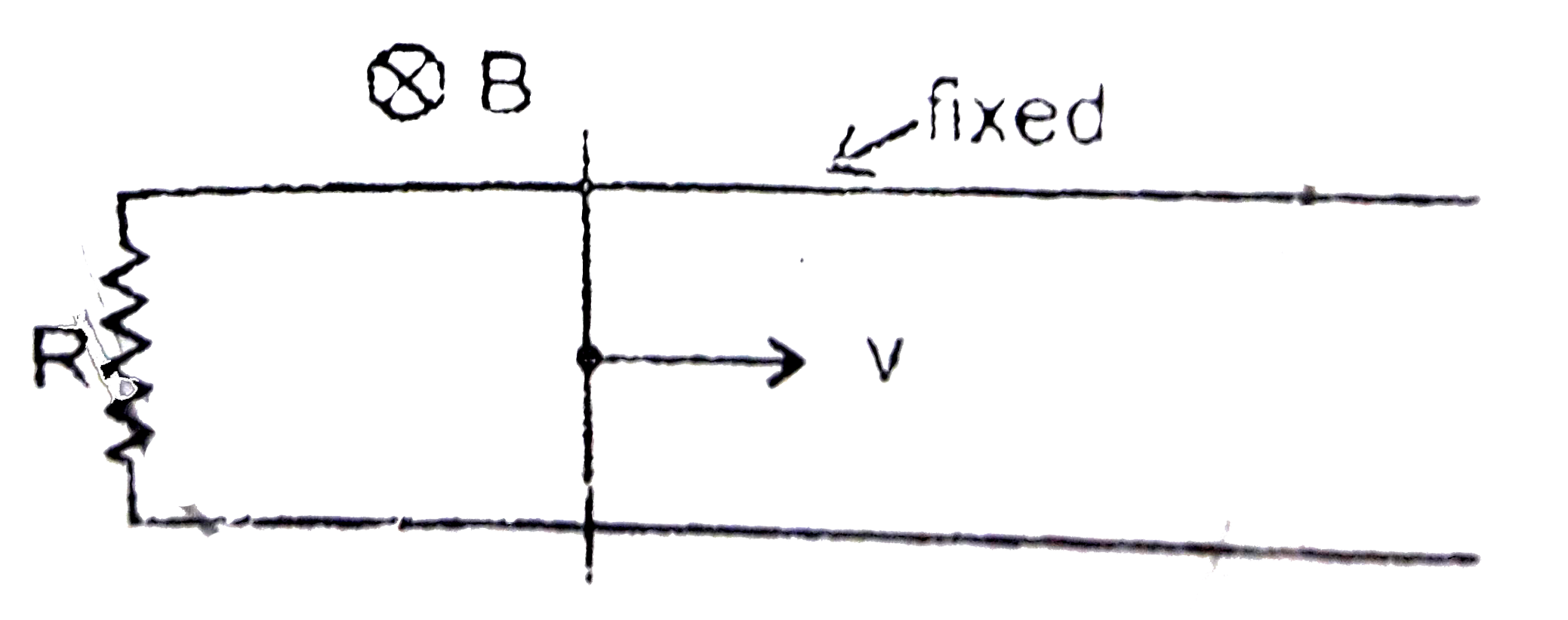
The total work done by magnetic field is negative.
The total work done by magnetic field is positive.
The total work done by magnetic field is zero.
loss in kinetic energy of conducting rod is equal to heat generate between .
The correct Answer is:C, D
Magnetic field cannot do work
Topper's Solved these Questions
- ELECTROMAGNETIC INDUCTIONBOOK - RESONANCE ENGLISHCHAPTER - ELECTROMAGNETIC INDUCTIONEXERCISE - Exercis-2 PART 4
6 Videos
- ELECTROMAGNETIC INDUCTIONBOOK - RESONANCE ENGLISHCHAPTER - ELECTROMAGNETIC INDUCTIONEXERCISE - Exercis-3 PART 1
18 Videos
- ELECTROMAGNETIC INDUCTIONBOOK - RESONANCE ENGLISHCHAPTER - ELECTROMAGNETIC INDUCTIONEXERCISE - Exercis-2 PART 2
17 Videos
- ELECTRODYNAMICSBOOK - RESONANCE ENGLISHCHAPTER - ELECTRODYNAMICSEXERCISE - Advanced level problems
31 Videos
- ELECTROSTATICSBOOK - RESONANCE ENGLISHCHAPTER - ELECTROSTATICSEXERCISE - HLP
40 Videos
Similar Questions
Statement I: A resistance R is connected between the two ends of the parallel smooth conducting rails. A conducting rod lies on these fixed horizontal rails and a uniform constant magnetic field B exists perpendicular to the plane of the rails as shown in Fig. if the rod is given a velocity υ and released as shown in Fig. 3.188, it will stop after some time. the total work done by magnetic field negative.
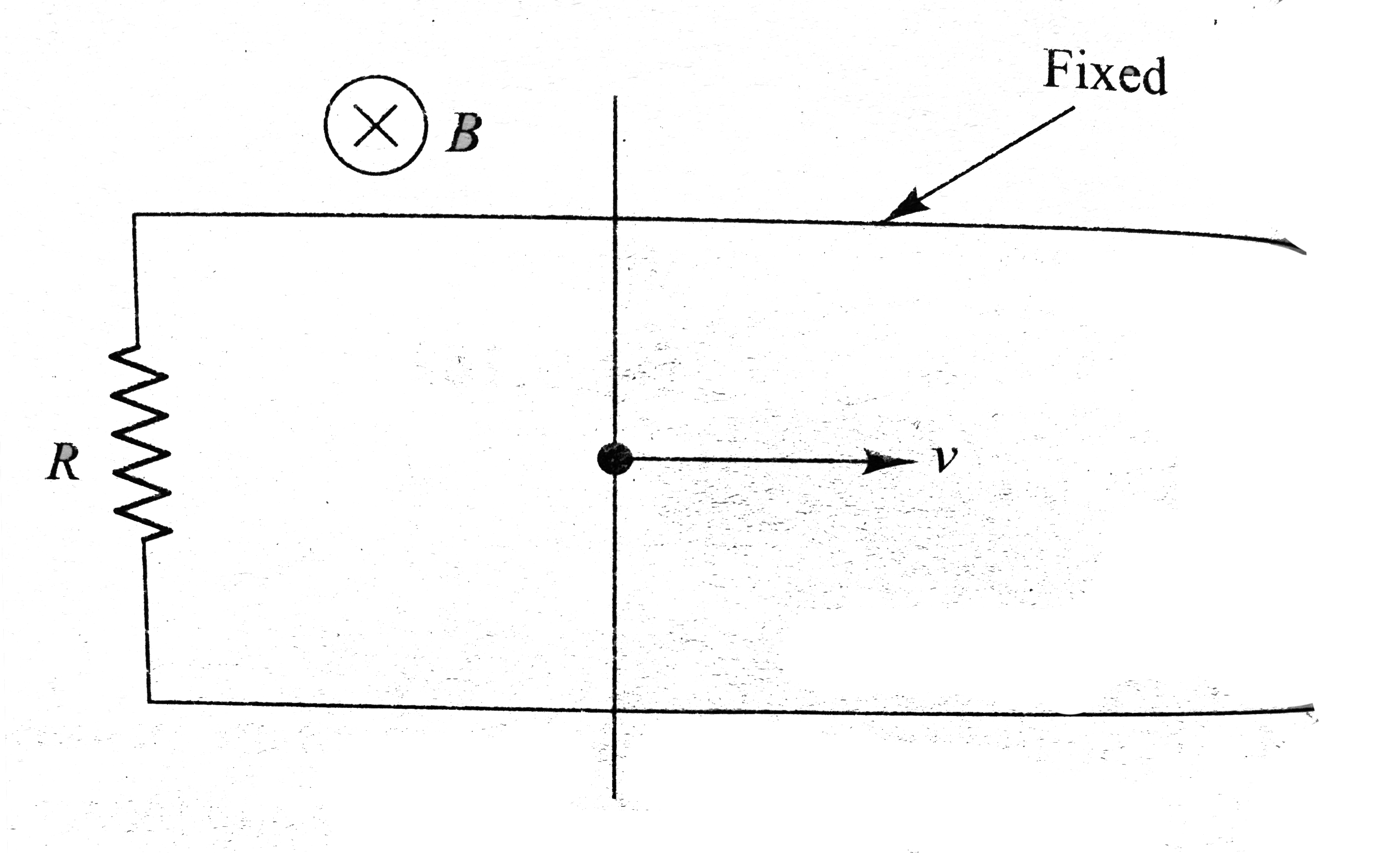
Statement II: If force acts opposite to direction of velocity its work done is negative.
View SolutionA conducting rod of length is moved at constant velocity v0 on two parallel, conducting, smooth, fixed rails, that are placed in a uniform constant magnetic field B perpendicular to the plane for the rails as shown in Fig. A resistance R is connected between the two ends of the rails.
Then which of the following is/are correct:

View SolutionA conducting wire xy of lentgh l and mass m is sliding without friction on vertical conduction rails ab and cd as shown in figure. A uniform magnetic field B exists perpendicular to the plane of the rails, x moves with a constant velocity of
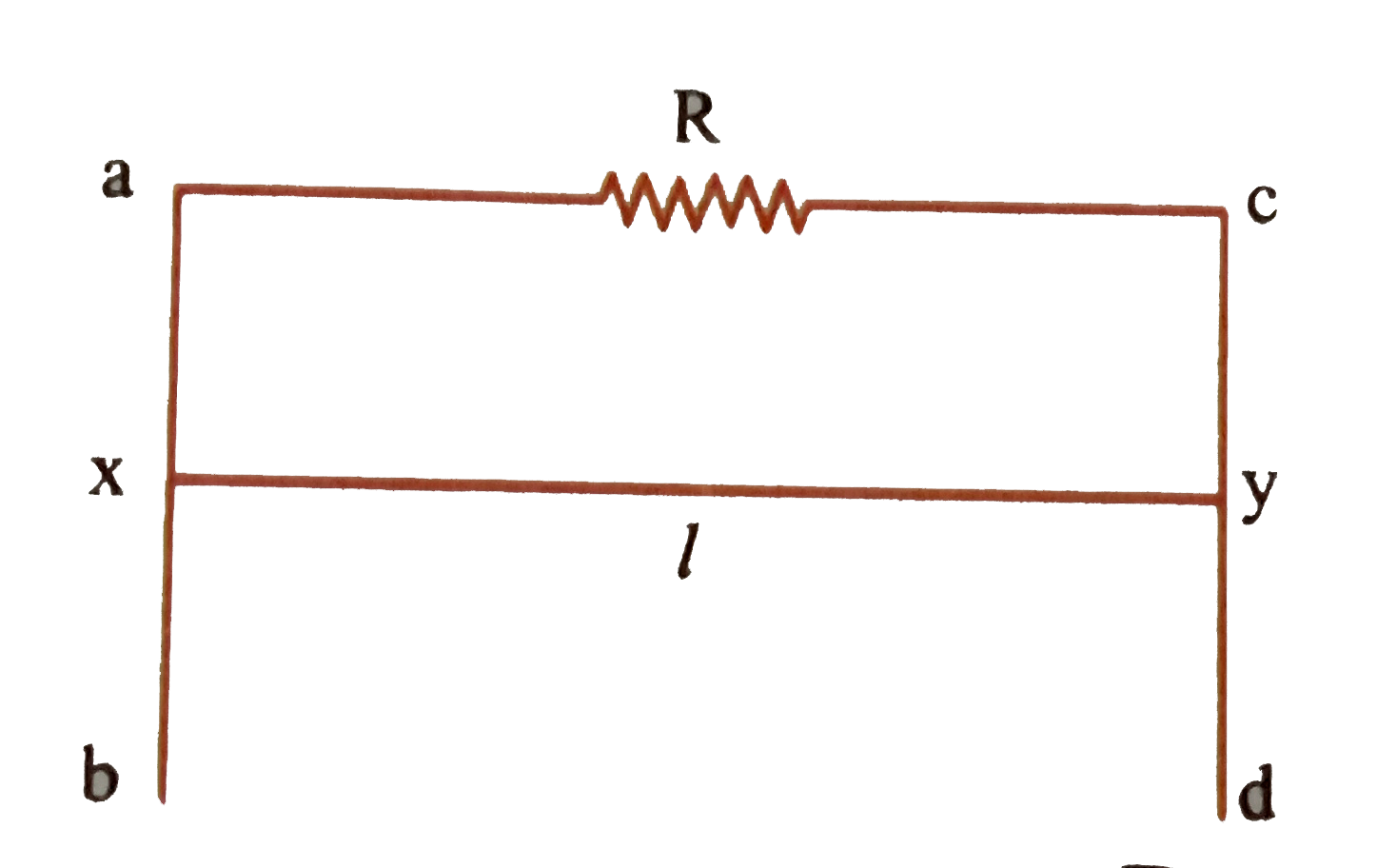
View SolutionA conducting wire xy of lentgh l and mass m is sliding without friction on vertical conduction rails ab and cd as shown in figure. A uniform magnetic field B exists perpendicular to the plane of the rails, x moves with a constant velocity of

View SolutionA conducting rod AB of length l is rotated about point O with an angular velocity velocity omega in a uniform magnetic field (B_0) directed perpendicular into the plane of rotation as shown in the figure. The value of VB−VA is
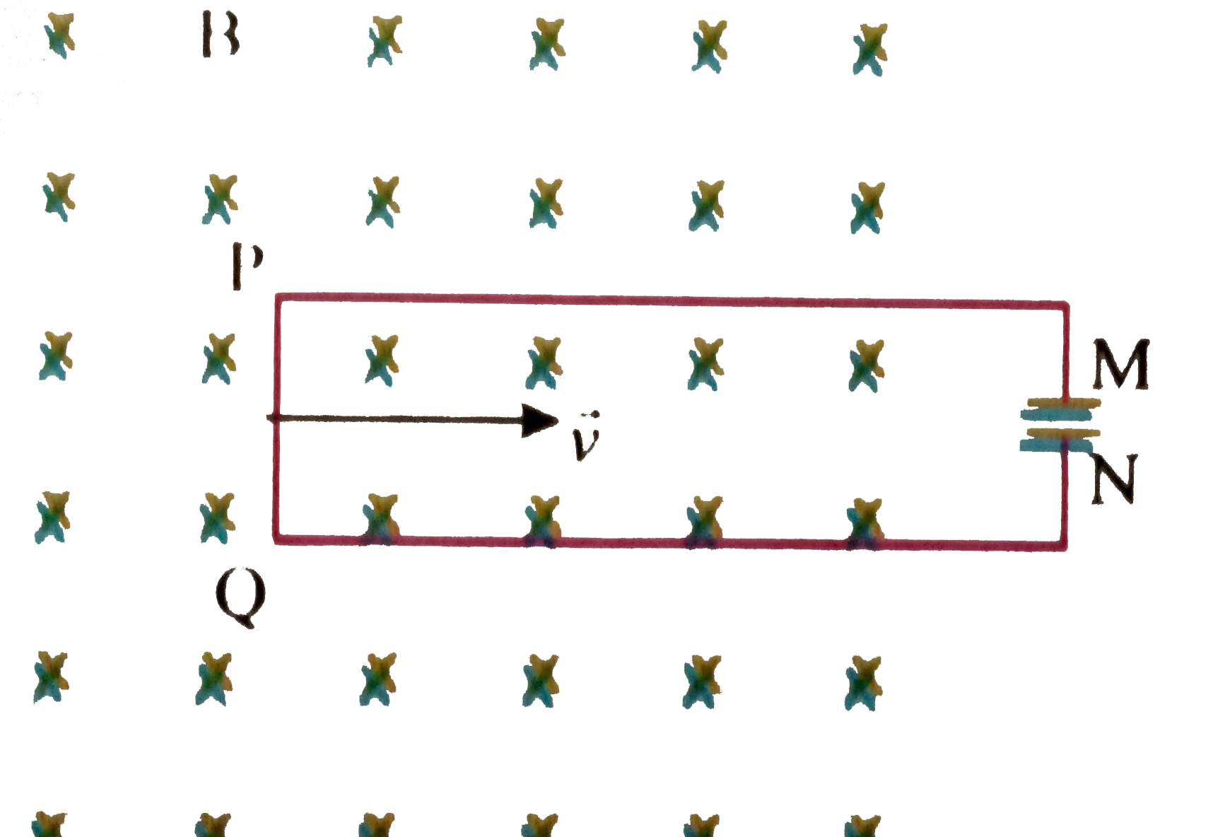
View SolutionA rod PQ is connected to the capacitor plates. The rod is placed in a magnetic field (B) directed downwards perpendicular to the plane of the paper. If the rod is pulled out of magnetic field with velocity →v as shown in Figure.
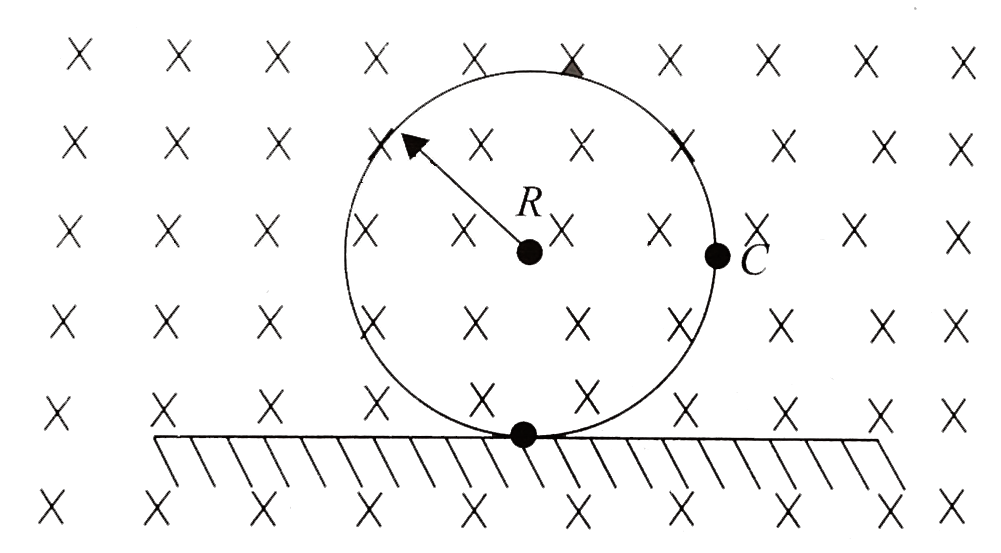
View SolutionA ring of radius R is rolling on a horizontal plane with constant velocity v. There is a constant and uniform magnetic field B which is perpendicular to the plane of the ring. Emf across the lowest point A and right-most point C as shown in the figure will
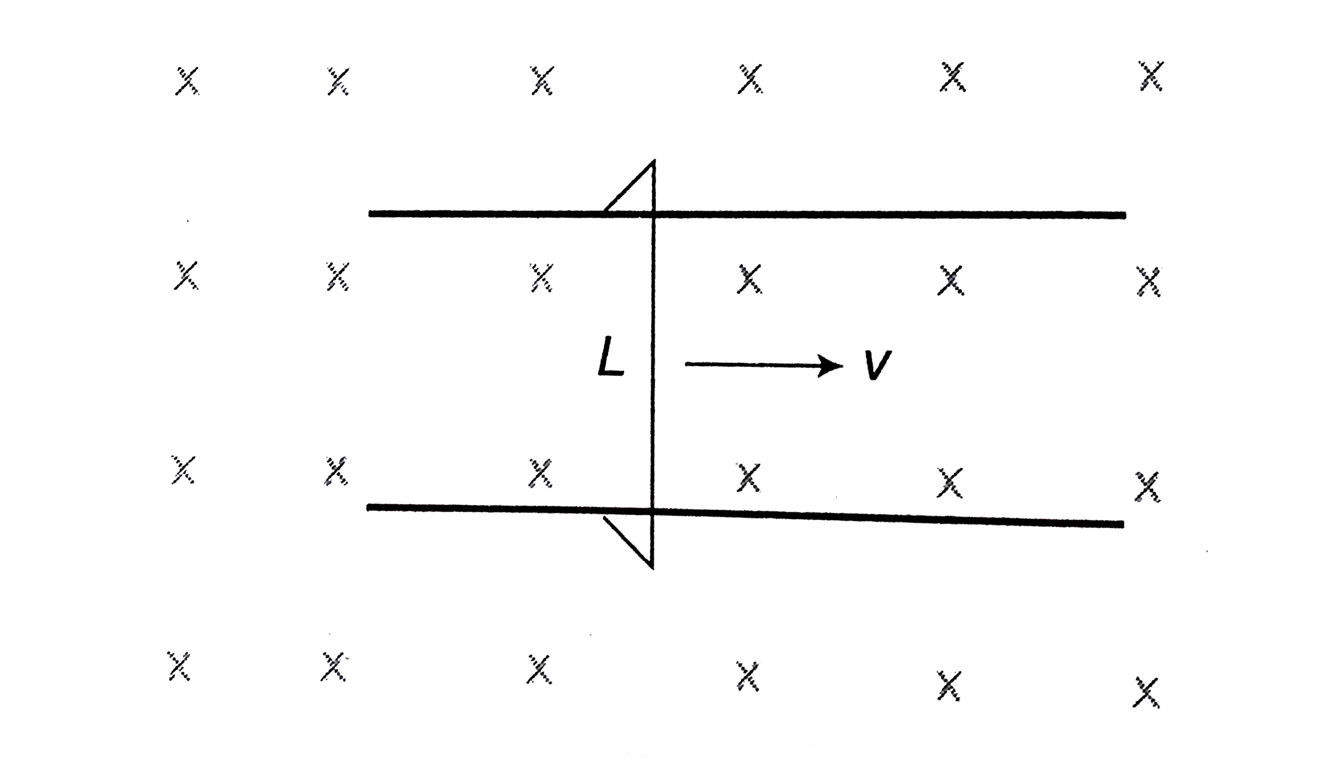
View SolutionFigure shows a wire sliding on two parallel, conducting rails placed at a separation L . A magnetic field B exists in a direction perpendicular to the plane of the rails. What force is necessary to keep the wire moving at a constant velocity V ?
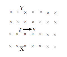
View SolutionA small conducting rod of length l, moves with a uniform velocity v in a uniform magnetic field B as shown in fig __
View Solution
