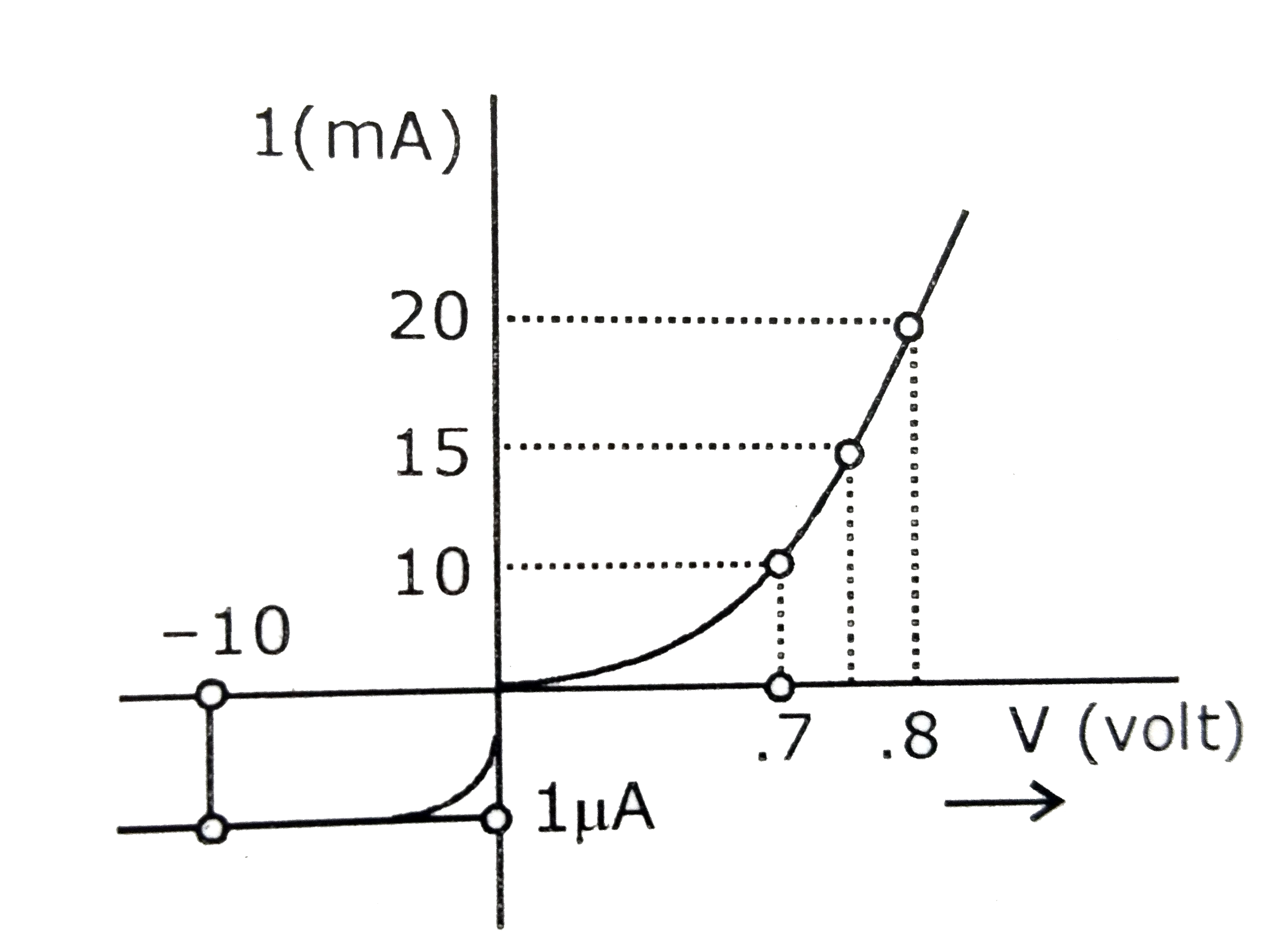
The i-V characteristic of a p-n junction diode is shown in figure.Find the approximate dynamic resistance of the p-n junction when (a) a forward bias of 1 volt is applied ,(b) a forward bias of 2 volt is applied is applied .
(##HCV_VOL2_C45_S01_003_Q01##)
The current at 1 volt is 10 mA and at 1.2 volt it is 15 mA. The dynamic resistance in this region is
R=ΔVΔi=0.2volt5mA=40Ω
(b). The current at 2 volt is 400 mA and at 2.1 volt it is 800 mA. The dynamic resistance in the region is
R=ΔVΔi=0.1volt400mA=0.25Ω.
Topper's Solved these Questions
- SEMICONDUCTORSBOOK - RESONANCE ENGLISHCHAPTER - SEMICONDUCTORSEXERCISE - Exercise
100 Videos
- SEMICONDUCTORSBOOK - RESONANCE ENGLISHCHAPTER - SEMICONDUCTORSEXERCISE - Exercise 2
16 Videos
- REVISION DPPBOOK - RESONANCE ENGLISHCHAPTER - REVISION DPPEXERCISE - All Questions
463 Videos
- SIMPLE HARMONIC MOTION BOOK - RESONANCE ENGLISHCHAPTER - SIMPLE HARMONIC MOTION EXERCISE - Advanced Level Problems
13 Videos
Similar Questions
The V-I characteristic of a diode is shown in the figure. The ratio of forward to reverse bias resistance is

View SolutionThe V-I characteristic of a diode is shown in the figure. The ratio of forward to reverse bias resistance is

View SolutionForward bias characteristics of a p -n junction diode is used in which of the following devices ?
View SolutionWhen a forward bias is applied to a p -n junction. It
View SolutionIn V-I characteristics of a p-n junction diode, why is the current under reverse bias almost independent of the applied potential upto a critical voltage?
View SolutionIn a reverse biased p-n junction, when the applied bias voltages is equal to the breakdown voltage, then
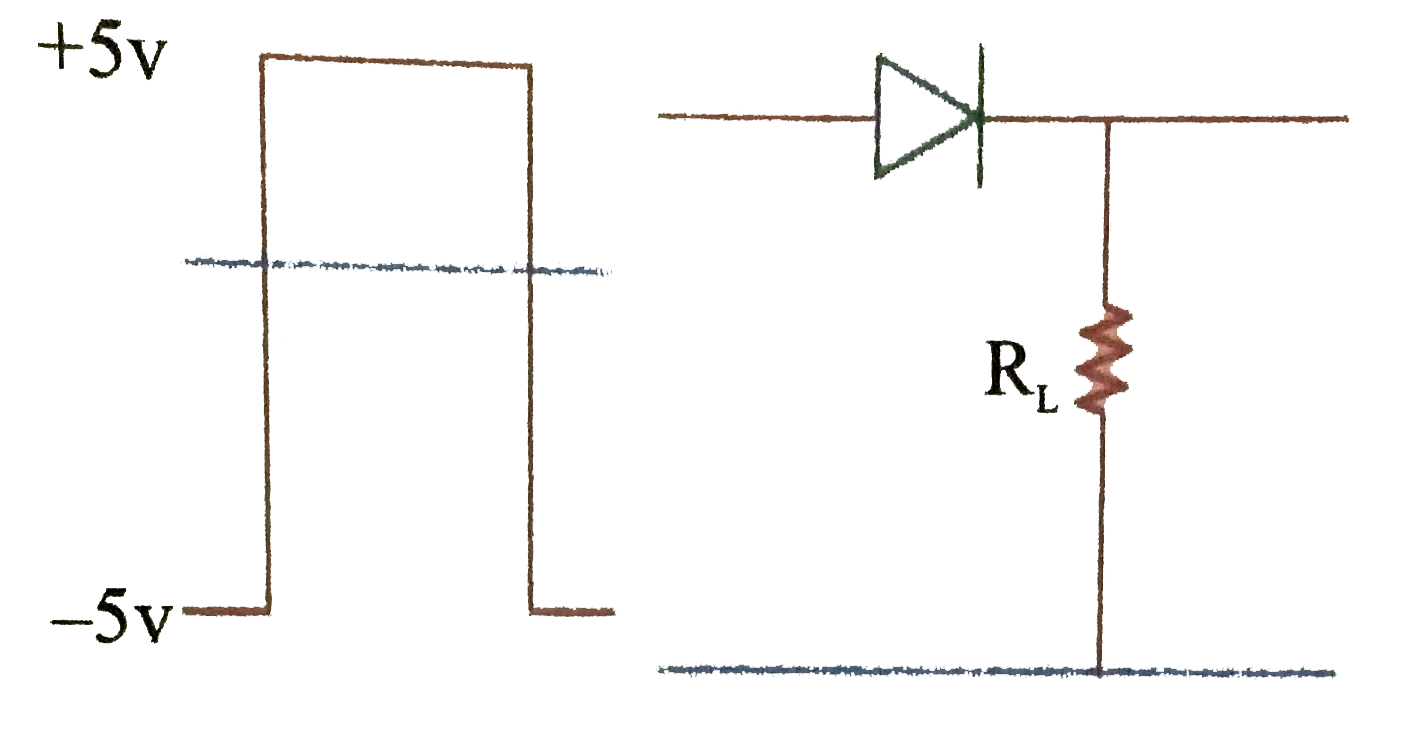
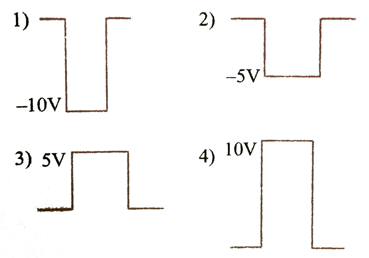
View SolutionIf in p-n junction diode a sinusoidal input signal is applied as shown Then the output signal across RL will bw
View SolutionA p-n junction in series with a resistance of 5kΩ is connected across a 50 V DC source . If the forward bias resistance of the junction is 50Ω , the forward bias current is
View SolutionIf a p−n junction diode, a square input signal of 10V is applied as shown.

Then the out put signal across RL will be
 .
.
View SolutionA square wave (-1 to +1V) is applied to a P-N junction diode as shown. Draw the output wave form across the diode which is assumed to be ideal-

View Solution
