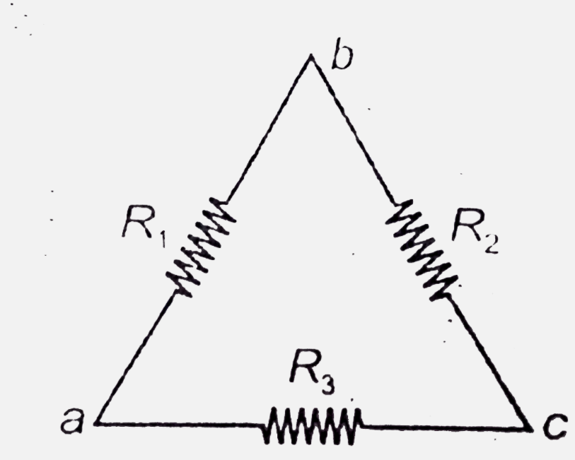
Consider the circuit shown in the figure. Equivalent resistance between terminals ab,ac,c equals 30Ω,60Ω and 70Ω respectively. Find the respectively . Find the resistance R1,R2and R3
34Ω,170Ω,85Ω
Topper's Solved these Questions
- CURRENT ELECTRICITYBook:AAKASH INSTITUTE ENGLISHChapter:CURRENT ELECTRICITYExercise:ASSIGNMENT SECTION-I(SUBJECTIVE TYPE QUESTIONS)
Explore 14 Videos
- COMMUNICATION SYSTEMS Book:AAKASH INSTITUTE ENGLISHChapter:COMMUNICATION SYSTEMS Exercise:ASSIGNMENT SECTION D (Assertion-Reason)
Explore 10 Videos
- DUAL NATURE OF RADIATION AND MATTER Book:AAKASH INSTITUTE ENGLISHChapter:DUAL NATURE OF RADIATION AND MATTER Exercise:ASSIGNMENT (SECTION-D)
Explore 10 Videos
Similar Questions
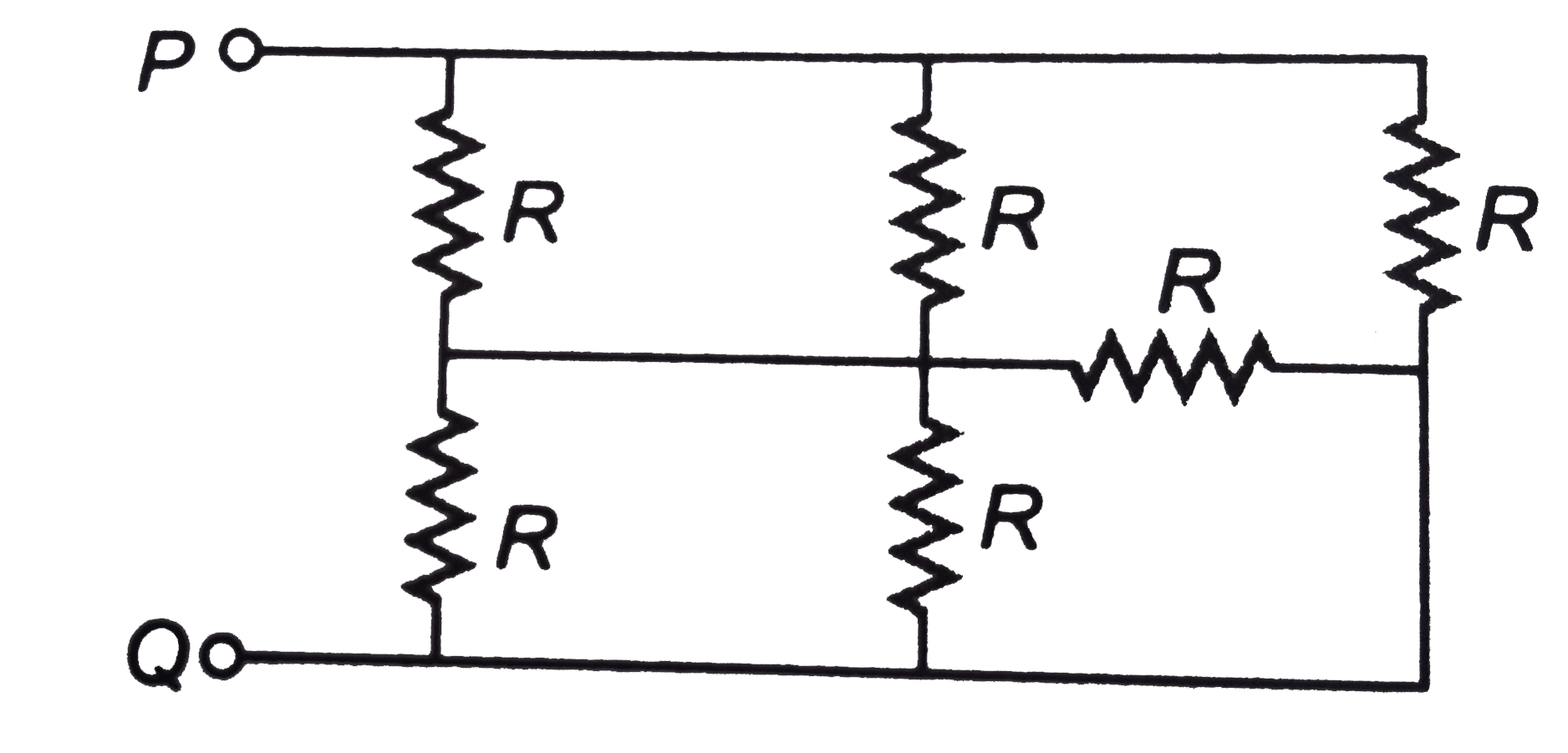
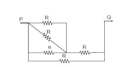
In the circuit shown in figure R=55Ω the equivalent resistance between the point P and Q is
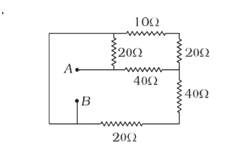
View SolutionIn the circuit shown in figure, the equivalent resistance between A and B is __________ Ω.
View SolutionEach resistance of the circuit shown in figure is r. The equivalent resistance between A and B is
View SolutionThe equivalent resistance between the terminal point P and Q is 4Ω in the given circuit, then find out the resistance of R in ohms
View SolutionConsider the circuit shown in fig.
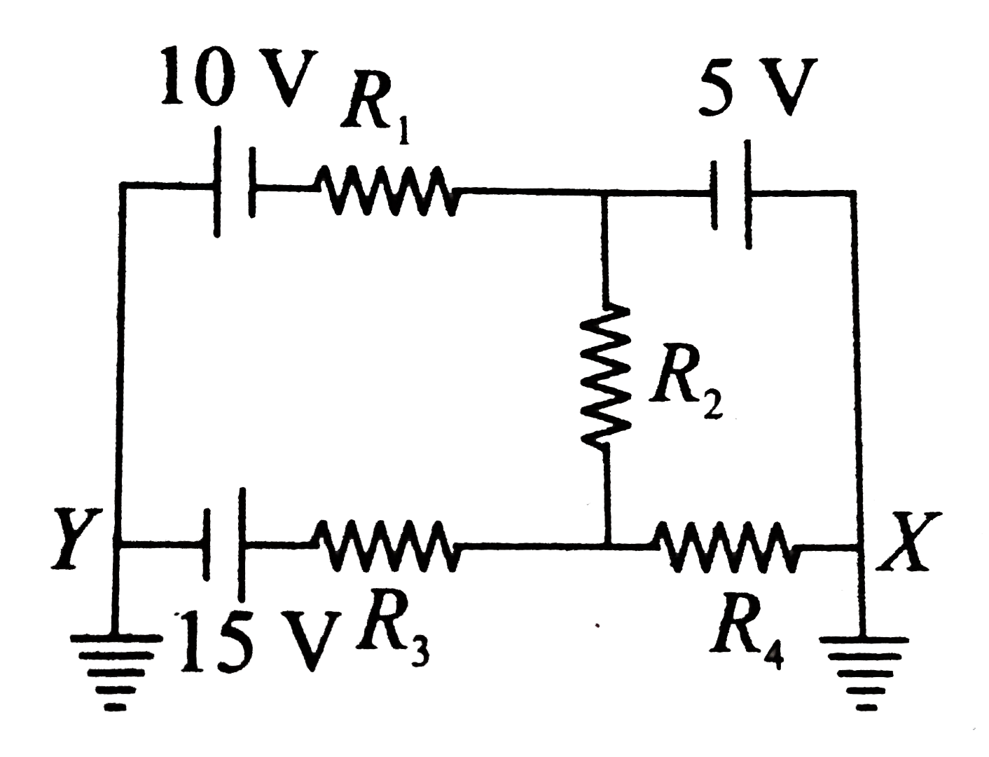
Assuming R1=2Ω, current passing through resistance R1 is
View SolutionThe power dissipated in the circuit shown in the figure is 30 W. The value of R is
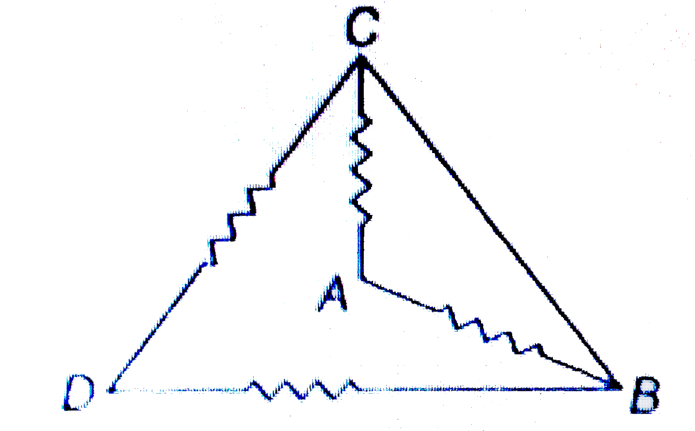
View SolutionThree resistors R1,R2 and R3 are to be combined to form an electrical circuit as shown in the figure. It is found that when R1R2andR3 are put respectively in positions A, B and C, the effective resistance of the circuit is 70 ΩWhen R2,R3andR1 are put respectively in position A, B and C the effective resistance is 35Ω and when R3,R1andR2 are respectively put in the position A, B and C, the effective resistance is 42Ω
If R1,R2 andR3are put in series, the effective resistance will be
View SolutionThree resistors R1,R2 and R3 are to be combined to form an electrical circuit as shown in the figure. It is found that when R1R2andR3 are put respectively in positions A, B and C, the effective resistance of the circuit is 70 ΩWhen R2,R3andR1 are put respectively in position A, B and C the effective resistance is 35Ω and when R3,R1andR2 are respectively put in the position A, B and C, the effective resistance is 42Ω
If R1,R2andR3 are all connected in parallel, the effective resistance will be
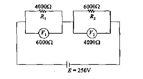
View SolutionIn the circuit shown in figure-3.391, V1andV2 are two voltmeters having resistances 6000Ωand4000Ω respectively EMF of battery is 250V, having negligible internal resistance. Two resistances R1andR2 are 4000Ωand6000Ω respectively. Find the reading of the voltamter V1andV2 when
(a) Switch S is open ltbgt (b) Switch S is closed
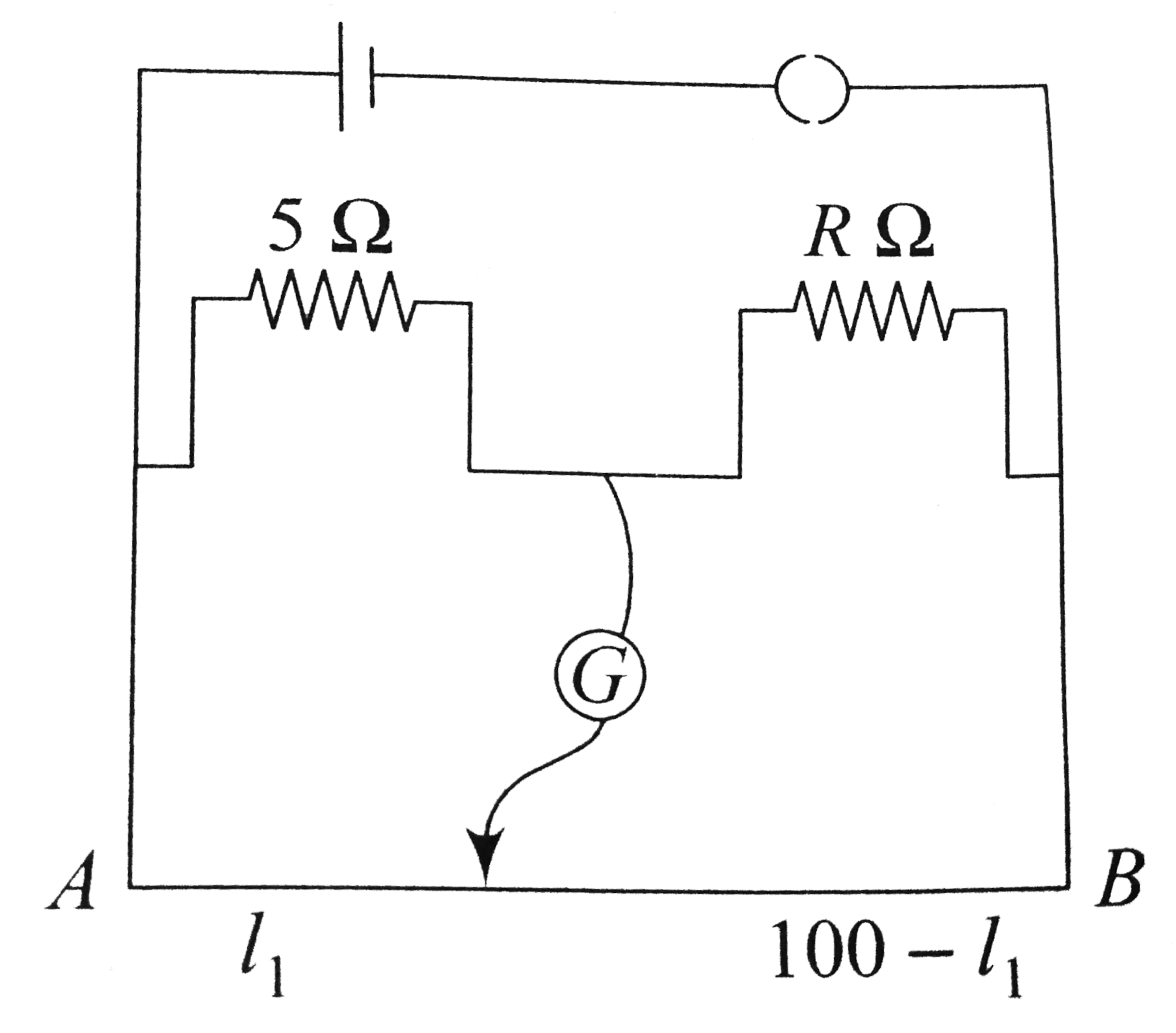
View SolutionThe resistance in the two arms of the meter bridge are 5Ω and RΩ, respectively. When the resistance R is shunted with an equal resistance, the new balance point is 1.6l1.
The resistance R is
View Solution

