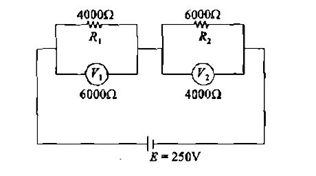
In the circuit shown in figure-3.391, are two voltmeters having resistances respectively EMF of battery is 250V, having negligible internal resistance. Two resistances are respectively. Find the reading of the voltamter when
(a) Switch S is open ltbgt (b) Switch S is closed
Similar Questions
The emf E and the internal resistance r of the battery shown in figure are 4.3V and 1.0Ω respectively. The external resistan ce R is 50Ω. The resistance of the ammeter and voltameter are 2.0Ω an d 200Ω respectively. Find the respective reading of the voltmeter.

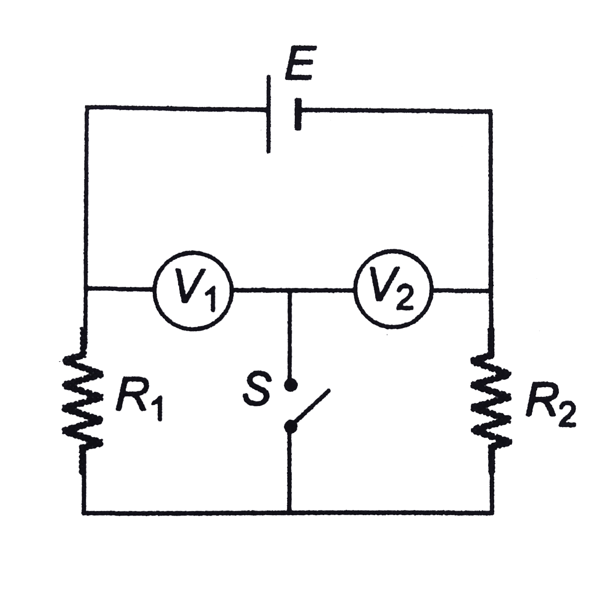
View SolutionIn the circuit shownin figure V1 and V2 are two voltmeter of resistances 3000Ω and 2000Ω respectively. In additions R1=2000Ω, R2=3000ω and E=200V then
a. Fid the reading of voltmeters V1 and V2 when
i. switch S is open
ii. Switch S is closed
b. Current through S, when it is closed (Disregard the resistance of battery)
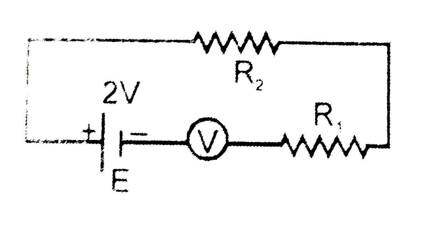
View SolutionA cell of e.m.f. 2V and negligible internal resistance is connected to resistor R1 and R2 as shown in the figure. The resistance of the Voltmeter R1 and R2 are 80Ω,40Ω and 80Ω respectively. The reading of the voltmeter is:-
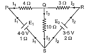
View SolutionIn the circuit shown in figure below, E1 and E2 are batteries having emfs 4.0 V and 3.5 V respectively and internal resistance 1Ω and 2Ω respectively. Using Kirchhoff.s laws, calculate currents : I1,I2 and I3.
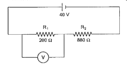
View SolutionFigure below shows two resistors R1andR2 connected to a battery having an emf of 40 V and negligible internal resistance. A voltmeter having a resistance of 300 Ω is used to measure potential difference across R1 Find the reading of the voltmeter.
View SolutionA 5 V battery of negligible internal resistance is connected across a 200 V battery and a resistance of 39Ω as shown in the figure. Find the value of the current.

View SolutionIn the ciruit the cells E1andE2 have emfs of 4V and 8V and internal resistance 0.5Ωand1.0Ω, respectively. Calculate the current through 6Ω resistance.

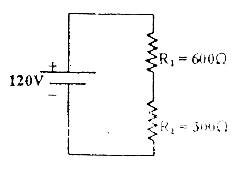
View SolutionA voltmeter of resistance 600Ω when connected in turn across resistances R1 and R2 gives readings of V1 and V2, respectively. If the battery is ideal, then
View SolutionIn the circuit shown E,F,G and H are cells of emf 2V,1V,3V and 1V respectively and their internal resistance are 2Ω,1Ω,3Ω and 1Ω respectively.
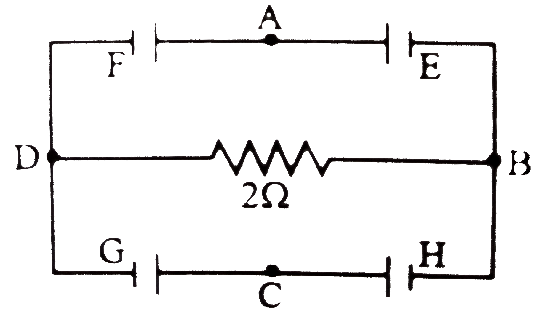
View SolutionIn the circuit shown E,F,G and H are cells of emf 2V,1V,3V and 1V respectively and their internal resistance are 2Ω,1Ω,3Ω and 1Ω respectively.

View Solution
