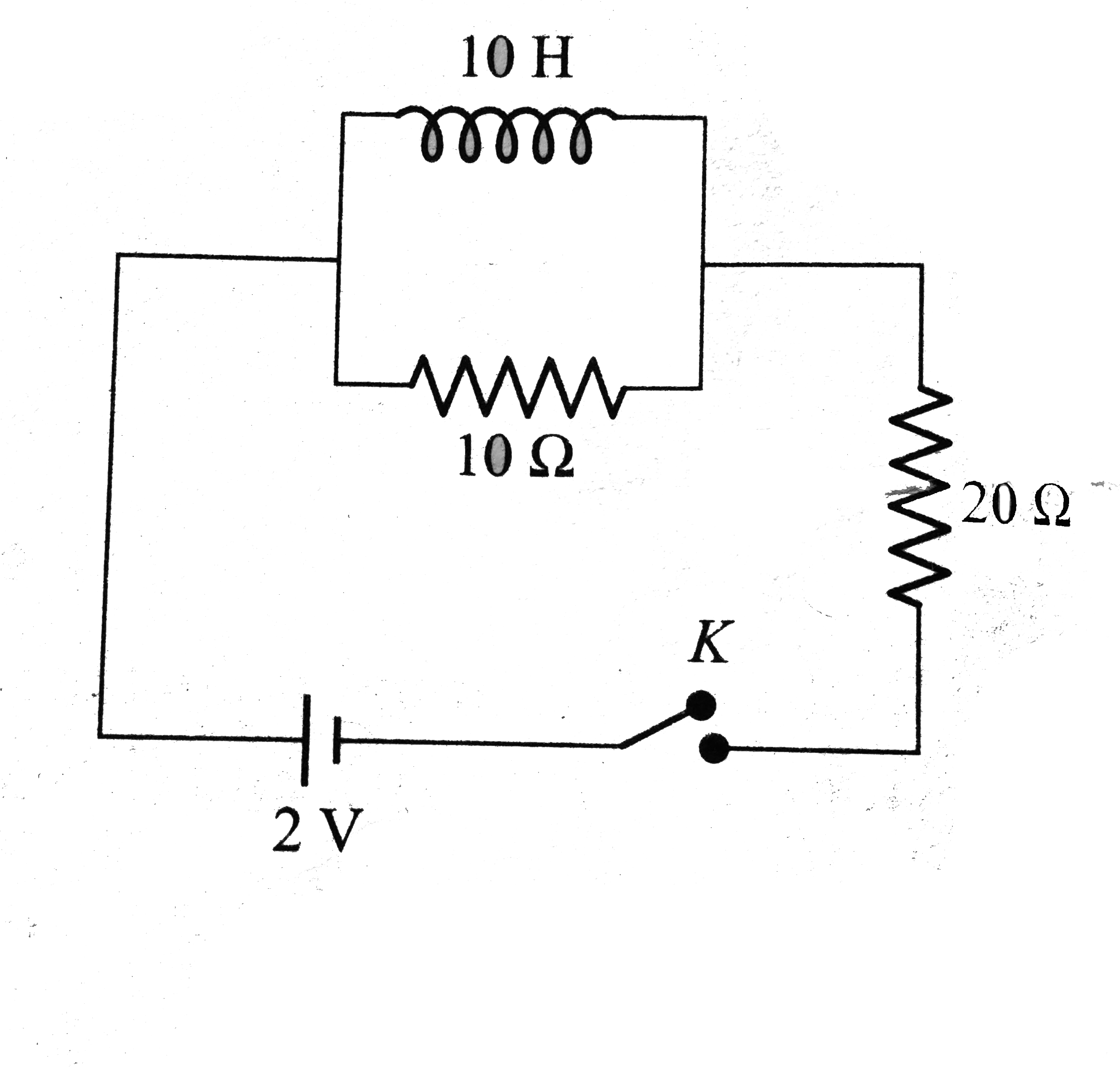
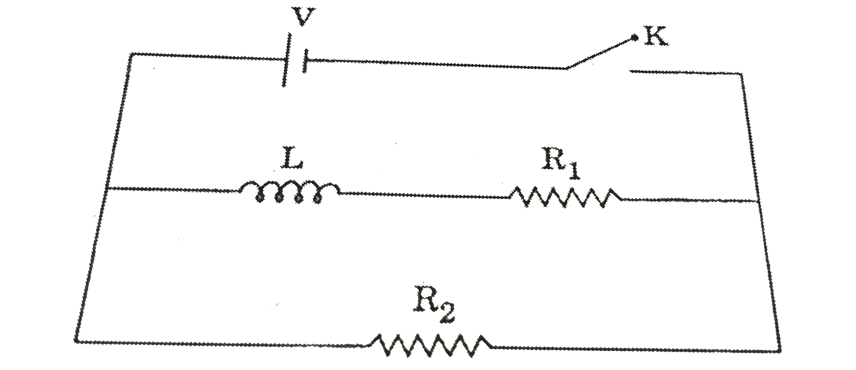
Two resistors of 10Ω and 20Ω and an ideal inductor of 10H are connected to a 2V battery as shows in Fig. key K is inserted at time t=0. The initial (t=0) and final (t→∞) currents through the battery are
115A,110A
110A,115A
215A,110A
115A,225A
The correct Answer is:A
At t=0,i.e., when the key is just pressed, no current exiests inside the inductor. So 10Ω and 20Ω resistance are in series and a net resistance of (10+20)=30Ω exists across the circuit.
Hence, I1=230=115A
As t→∞, the current in the inductor grows to attain a mximum value, i.e., the entrie current passes through the inductor and no current passes through 10Ω resistor.
Hence, I2=220=110A
Topper's Solved these Questions
- INDUCTANCEBOOK - CENGAGE PHYSICS ENGLISHCHAPTER - INDUCTANCEEXERCISE - Exercises (multiple Correct )
7 Videos
- INDUCTANCEBOOK - CENGAGE PHYSICS ENGLISHCHAPTER - INDUCTANCEEXERCISE - Exercises (assertion-reasoning)
2 Videos
- INDUCTANCEBOOK - CENGAGE PHYSICS ENGLISHCHAPTER - INDUCTANCEEXERCISE - Exercises (subjective)
7 Videos
- HEATING EFFECT OF CURRENTBOOK - CENGAGE PHYSICS ENGLISHCHAPTER - HEATING EFFECT OF CURRENTEXERCISE - Thermal Power in Resistance Connected in Circuit
27 Videos
- MAGNETIC FIELD AND MAGNETIC FORCESBOOK - CENGAGE PHYSICS ENGLISHCHAPTER - MAGNETIC FIELD AND MAGNETIC FORCESEXERCISE - Multiple Correct Answer type
2 Videos
Similar Questions
Two resistors of 2Ω and 4Ω and ideal inductor of 4H are connected to a 12V battery as given in the diagram.The steady current through the battery is
_PHY_E06_150_Q01.png)
View SolutionThree resistors 8Ω,12Ωand6Ω are connected to a 12 V battery as shown in Fig. below.

the current through the 6Ω resistor.
View SolutionThree resistors 8Ω,12Ωand6Ω are connected to a 12 V battery as shown in Fig. below.

the current through the 8 Ω resistor,
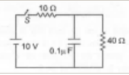
View SolutionTwo resistors of resistances 10Ω and 40Ω are connected with a capacitor of capacitance 0.1μF and ideal battery of emf 10 V. When switch (S) is closed, then initial current and current in steady state through the battery respectively are
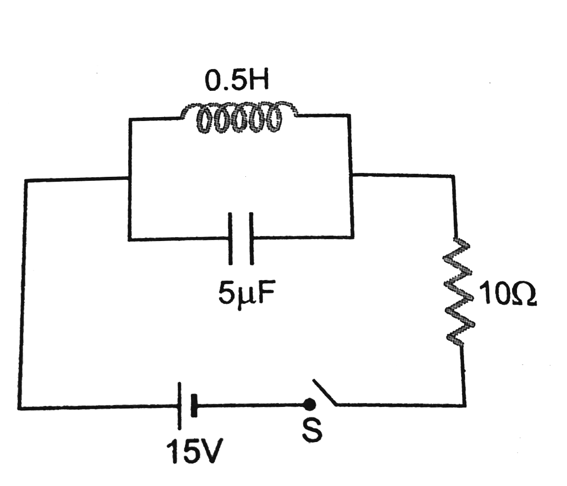
View SolutionIn the circuit shown in Fig. currrent through the battery at t=0 and t=∞ is
View SolutionIn the circuit shown below, the key K is closed at t =0. The current through the battery is
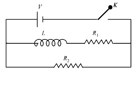
View SolutionIn the circuit shown below, the key K is closed at t = 0. The current through the battery is
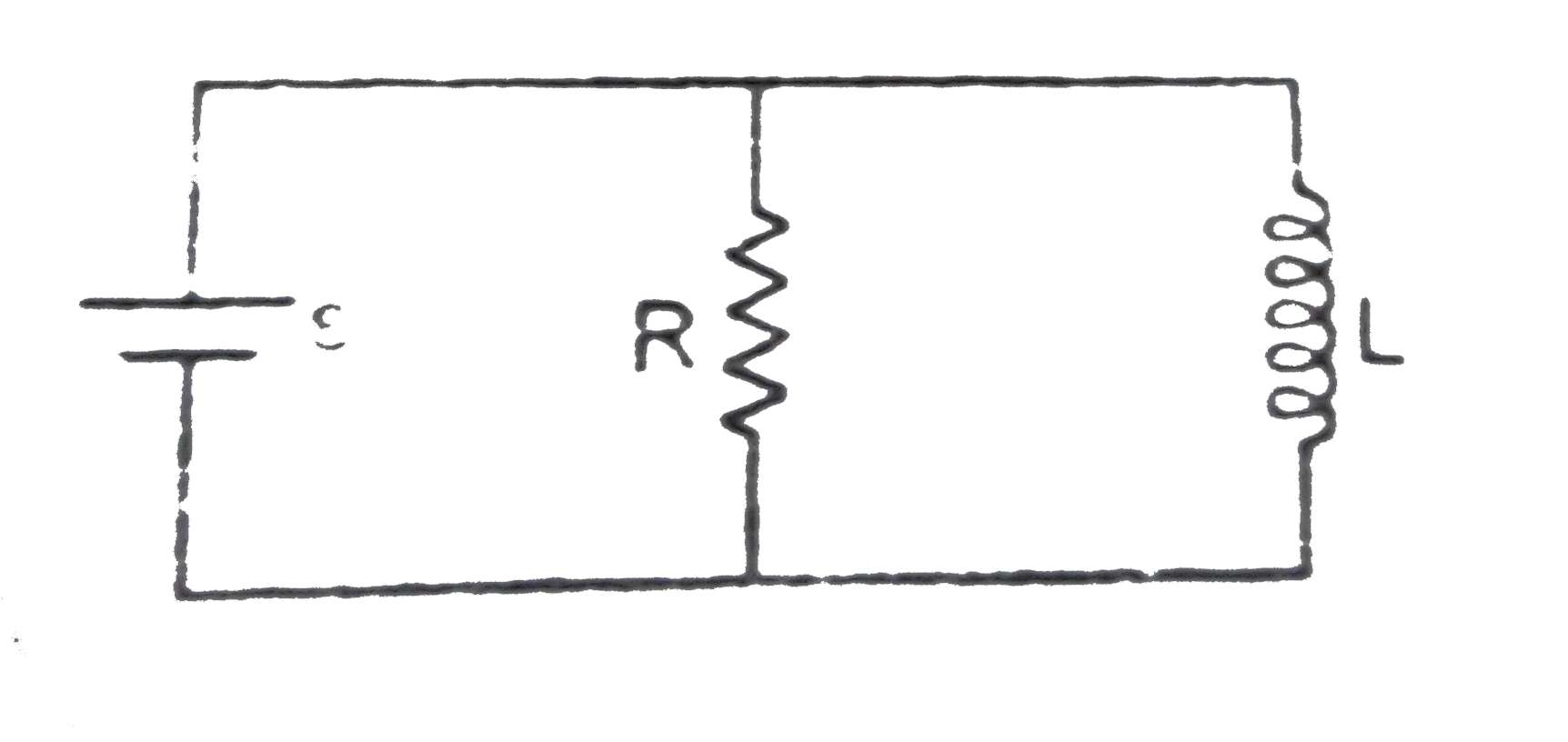
View SolutionThe battery shown in the figure is ideal.The values are ε=10V,R=5Ω,L=2H Intially the current in the inductor is zero.The current through the battery at t=2s is
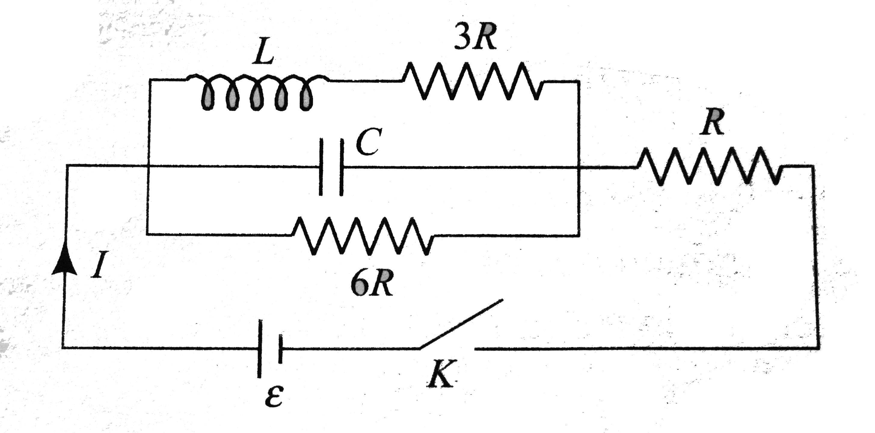
View SolutionIn the given circuit (Fig), key K is witched on the at t=0. The ratio of current i through the cell at t=0 to that at t=∞ will be
View SolutionTwo resistors of 4 Ω and 6 Ω are connected in parallel. The combination is connected across a 6 V battery of negligible resistance. (i) Draw a circuit diagram. (ii) Calculate :the current through the battery
View Solution
