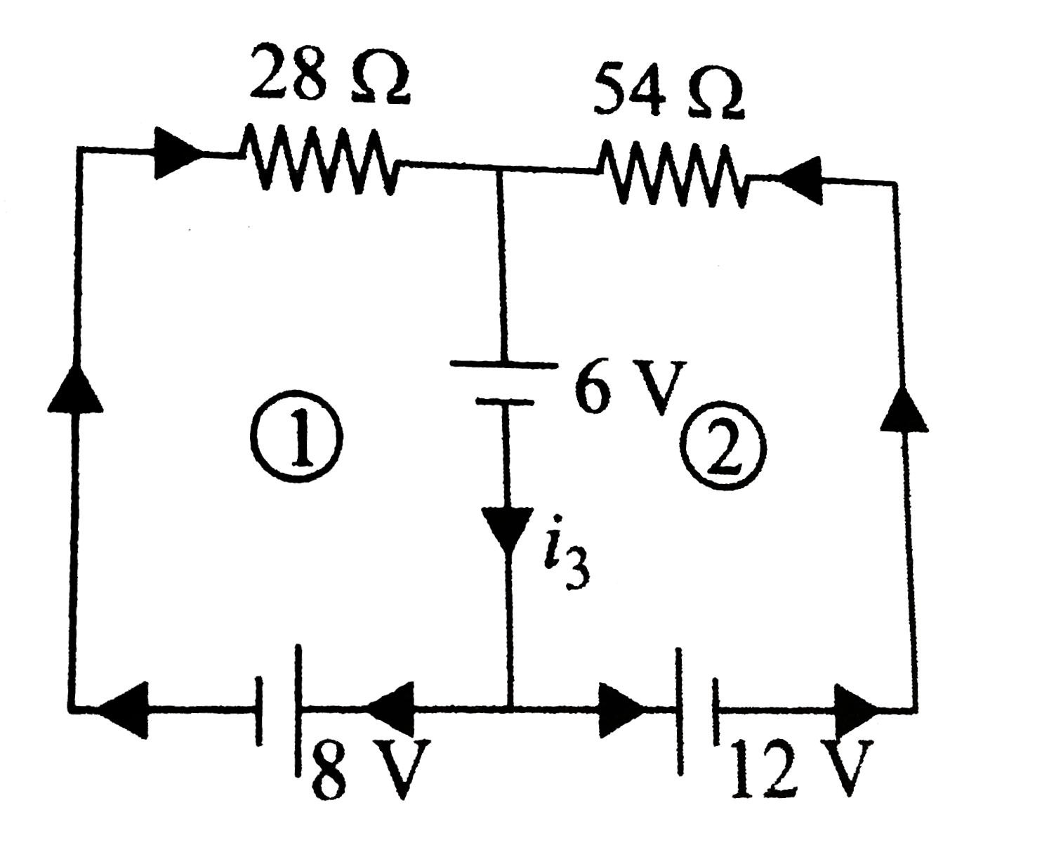
Consider the cicutir shown in fig. the current i3 is equal to
Suppose current through different paths of the circuit is as
follows.
After applying KVL for loop (1) and loop(2), we get
28if1=−6−8
or i1=−12
And 54i2=−6−12ori2=−13A
Hence i3=i1+i2=−56A
Topper's Solved these Questions
- ELECTRIC CURRENT AND CIRCUITBOOK - CENGAGE PHYSICS ENGLISHCHAPTER - ELECTRIC CURRENT AND CIRCUITEXERCISE - Subjective
29 Videos
- ELECTRIC CURRENT AND CIRCUITBOOK - CENGAGE PHYSICS ENGLISHCHAPTER - ELECTRIC CURRENT AND CIRCUITEXERCISE - Single Correct
72 Videos
- ELECTRIC CURRENT AND CIRCUITBOOK - CENGAGE PHYSICS ENGLISHCHAPTER - ELECTRIC CURRENT AND CIRCUITEXERCISE - Exercise 5.1
28 Videos
- ELECTRIC CURRENT & CIRCUITSBOOK - CENGAGE PHYSICS ENGLISHCHAPTER - ELECTRIC CURRENT & CIRCUITSEXERCISE - Kirchhoff s law and simple circuits
15 Videos
- ELECTRIC FLUX AND GAUSS LAWBOOK - CENGAGE PHYSICS ENGLISHCHAPTER - ELECTRIC FLUX AND GAUSS LAWEXERCISE - MCQ s
38 Videos
Similar Questions
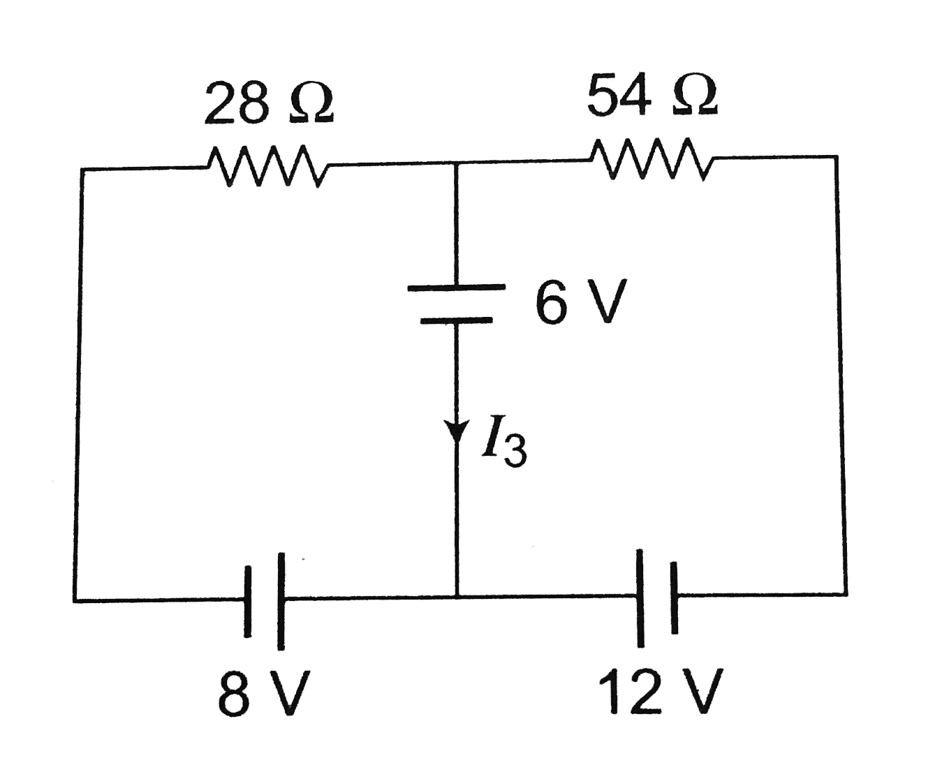
Consider the circuit shown in the figure. The current I3 is equal to
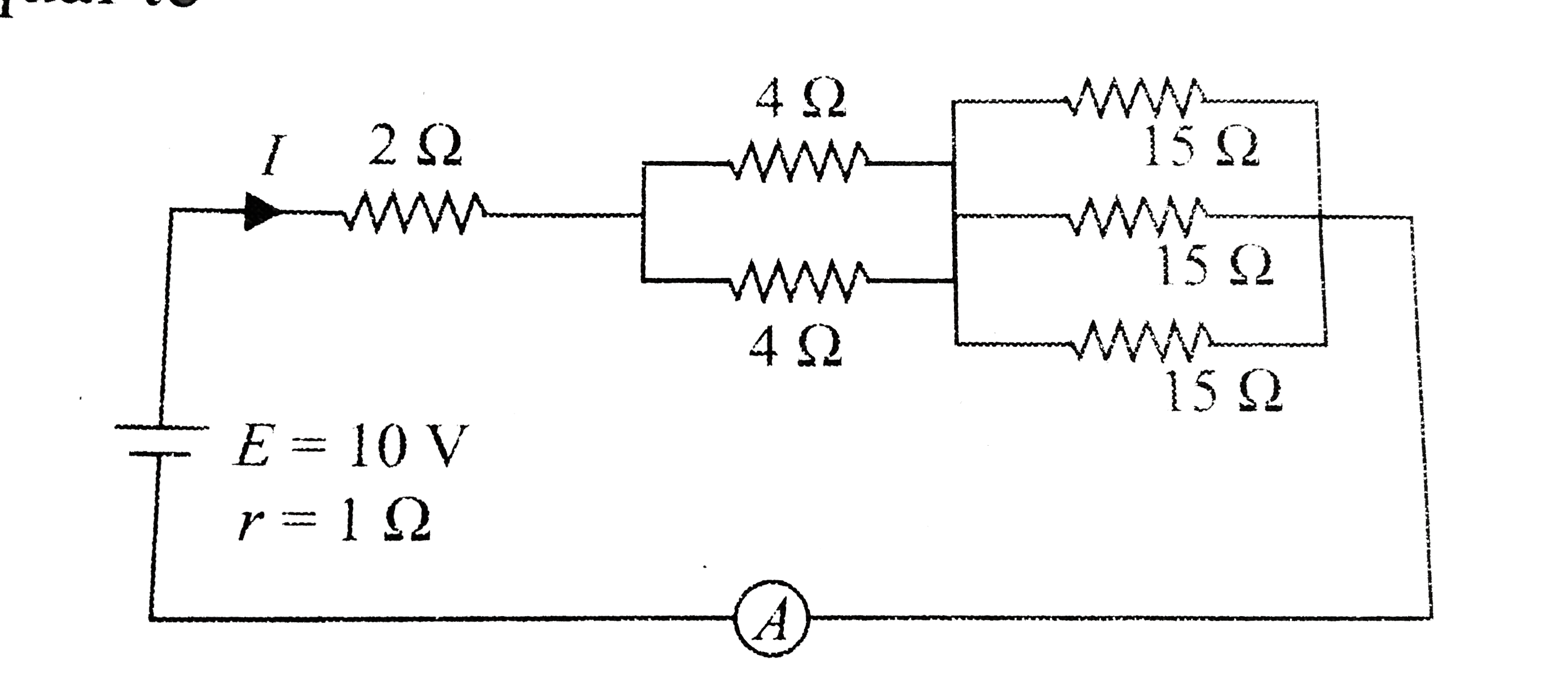
View SolutionIn the circuit shwon in fig. the current I has a value equal to
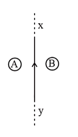
View SolutionConsider the situation shown in figure. If the current I in the long straight wire xy is increased at a steady rate the induced current in loop A and B will be
View SolutionConsider the circuit shown in fig.
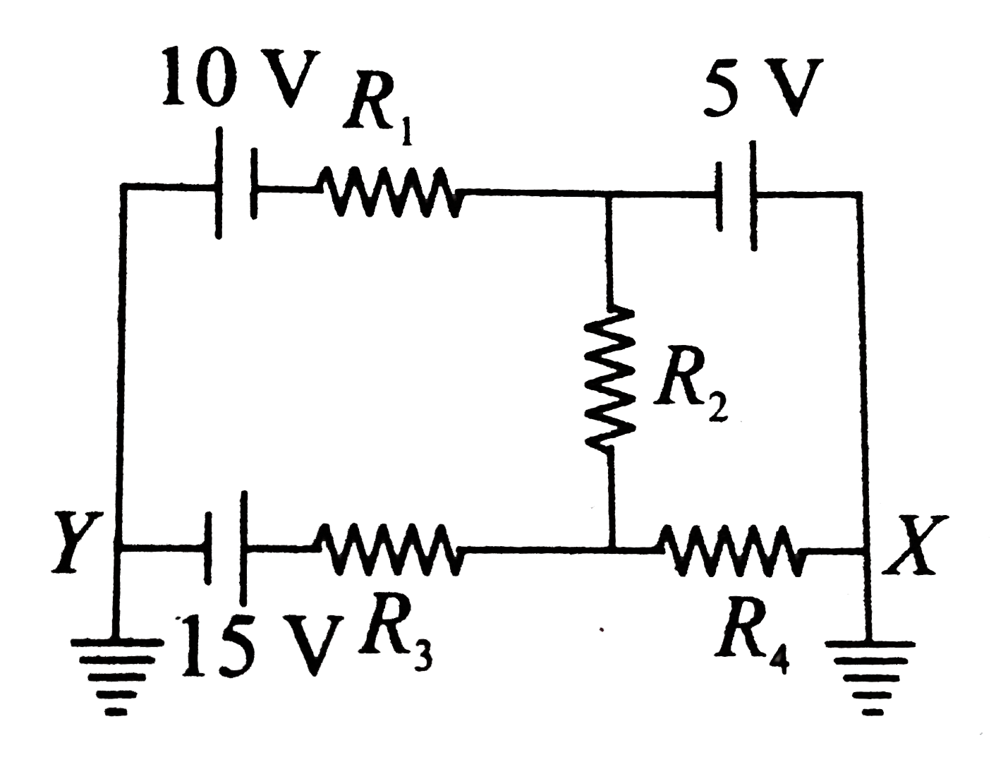
Current through R2 is zero if R4=2ΩandR3=4Ω in this case
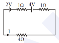
View SolutionFor the circuit shown in the figure current I will be
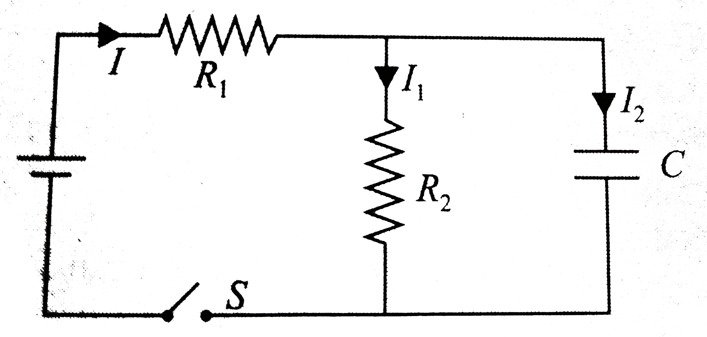
View SolutionConsider the circuit shown in fig. If the switch is closed at t =0, then calculate the values of I,I1 and I2 at a. t =0 , b. =∞
View SolutionConsider the circuit shwon in fig. The circuit is in steady state.
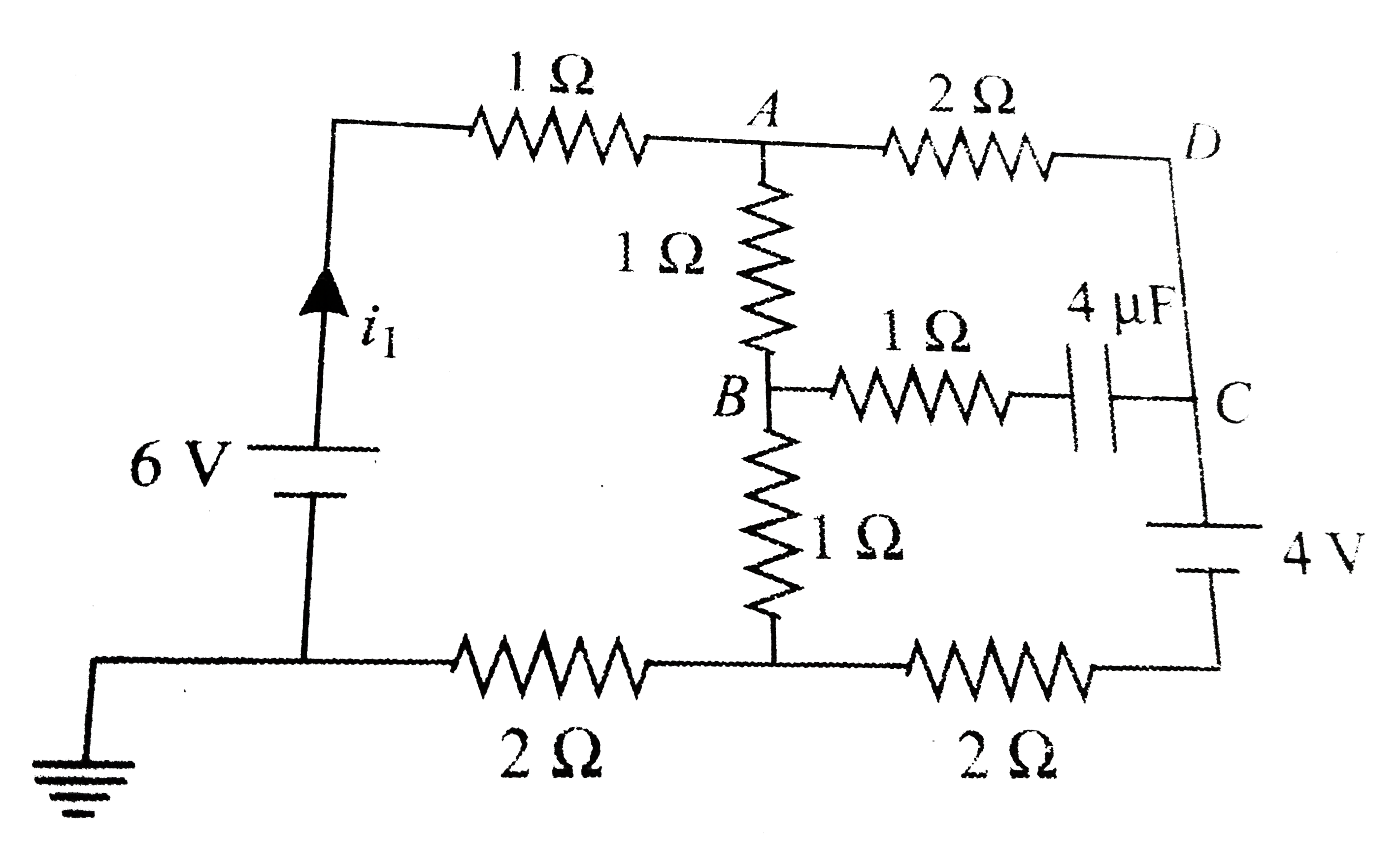
The value of i1 is
View SolutionIn the circuit shown in fig., the value of I1+I2 is
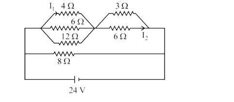
View SolutionIn the circuit shown in fig., the value of I1+I2 is

View SolutionConsider circuit as shown in figure. The current through wire AB is
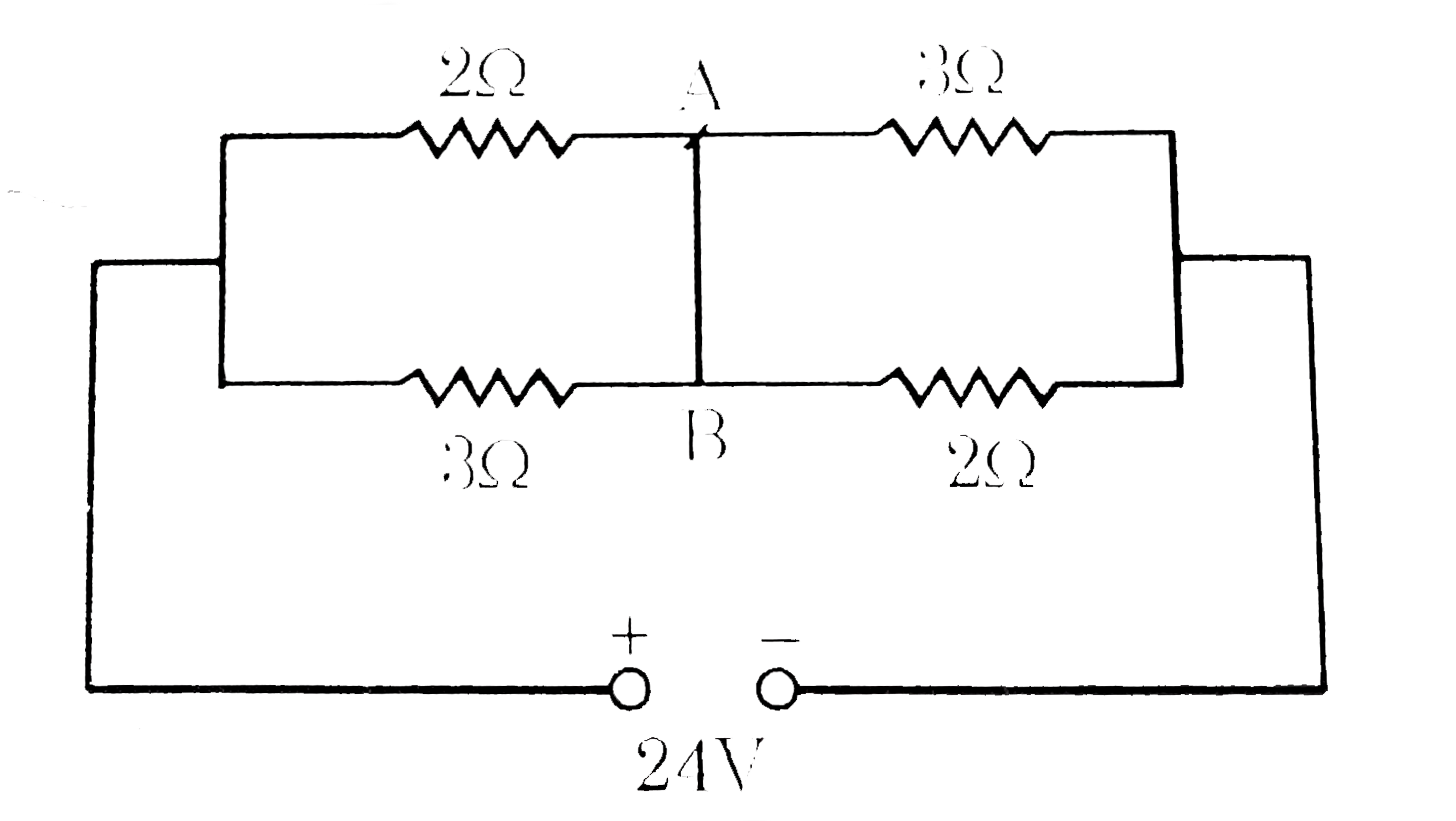
View Solution
