Consider the circuit shown in fig. If the switch is closed at t =0, then calculate the values of I,I1 and I2 at a. t =0 , b. =∞
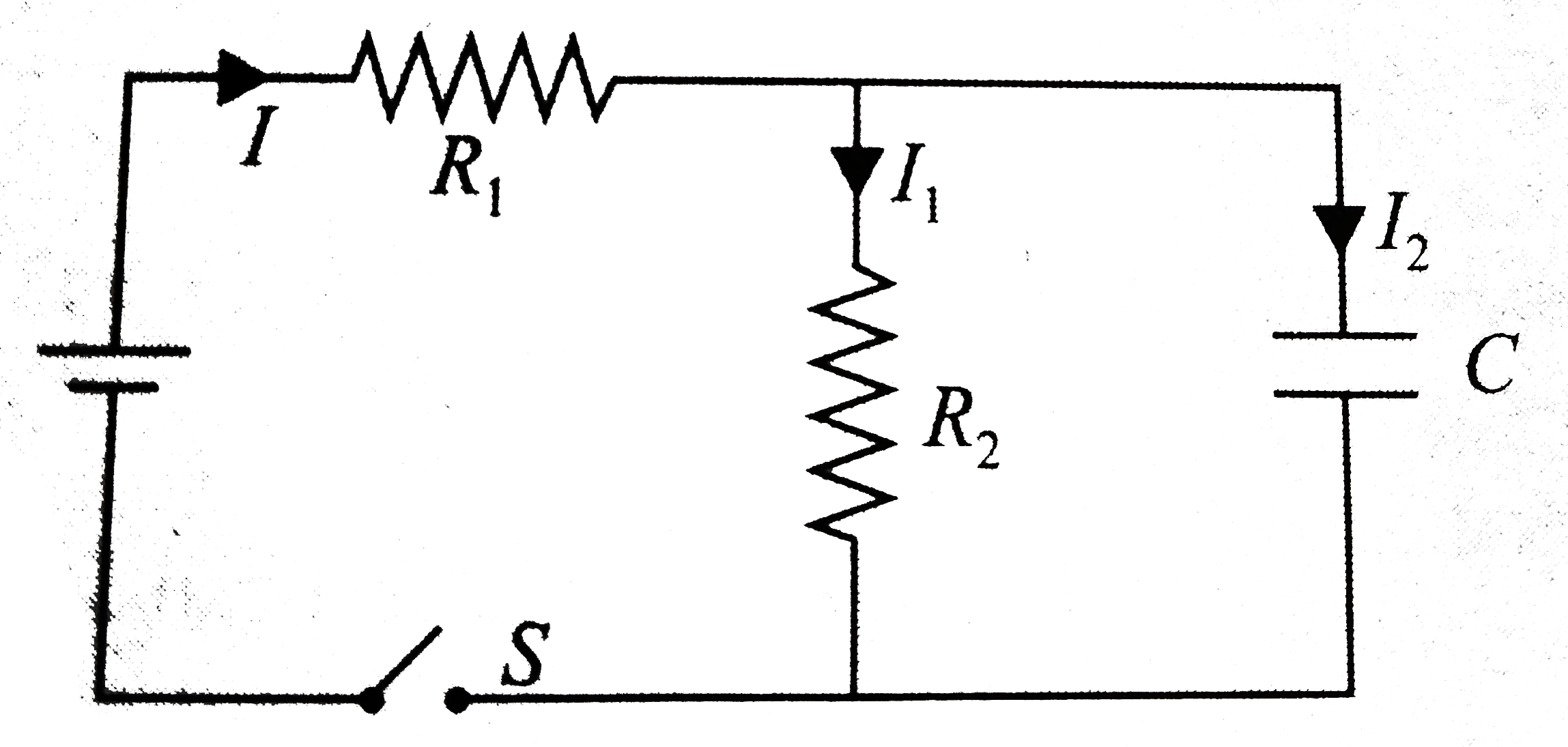
At t = 0, C wil behave as a short circuit, so no current
passes through R2 and I=I2=ε/R1.
b. Att=∞,C will block thr current. So I2=0. and
I=I1=εR1+R2
Topper's Solved these Questions
- BOOK - CENGAGE PHYSICS ENGLISHCHAPTER - ELECTRIC CURRENT AND CIRCUITEXERCISE - Subjective29videos
ELECTRIC CURRENT AND CIRCUIT
- BOOK - CENGAGE PHYSICS ENGLISHCHAPTER - ELECTRIC CURRENT AND CIRCUITEXERCISE - Single Correct72videos
ELECTRIC CURRENT AND CIRCUIT
- BOOK - CENGAGE PHYSICS ENGLISHCHAPTER - ELECTRIC CURRENT AND CIRCUITEXERCISE - Exercise 5.128videos
ELECTRIC CURRENT AND CIRCUIT
- BOOK - CENGAGE PHYSICS ENGLISHCHAPTER - ELECTRIC CURRENT & CIRCUITSEXERCISE - Kirchhoff s law and simple circuits15videos
ELECTRIC CURRENT & CIRCUITS
- BOOK - CENGAGE PHYSICS ENGLISHCHAPTER - ELECTRIC FLUX AND GAUSS LAWEXERCISE - MCQ s38videos
ELECTRIC FLUX AND GAUSS LAW
Similar Questions
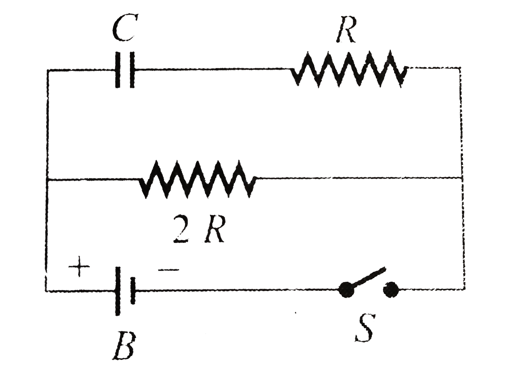
In the circuit shown in fig, if the switch S is closed at t=0 , the capacitor charges with a time constant
 View Solution
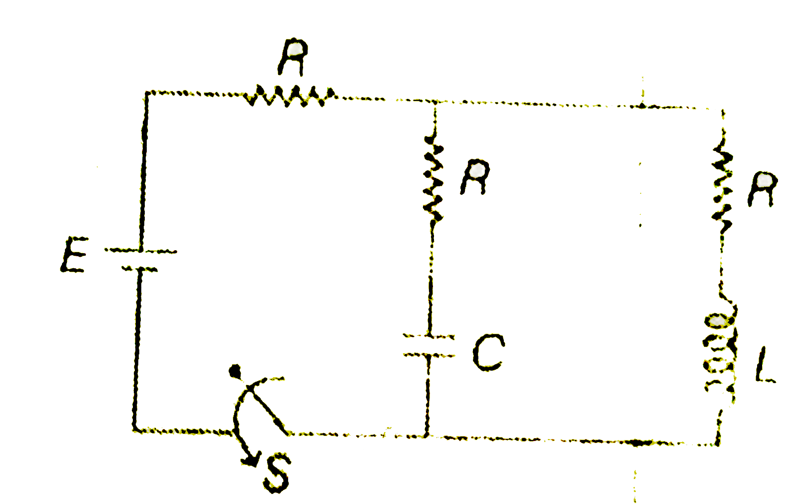
In the circuit as shown in the figure, switch S is added at t=0. Then:
 View Solution
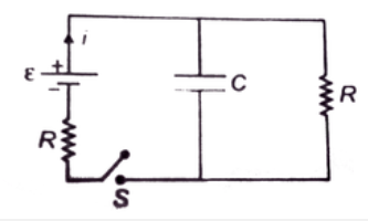
In the circuit shown, the switch is closed at t=0. Select the correct alternative(s)
 View Solution
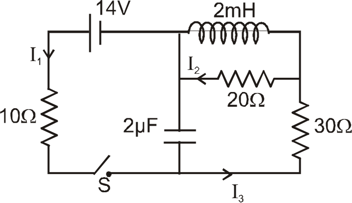
In the circuit shown, the switch is closed at t=0, the currents I1,I2 and I3 are
 View Solution
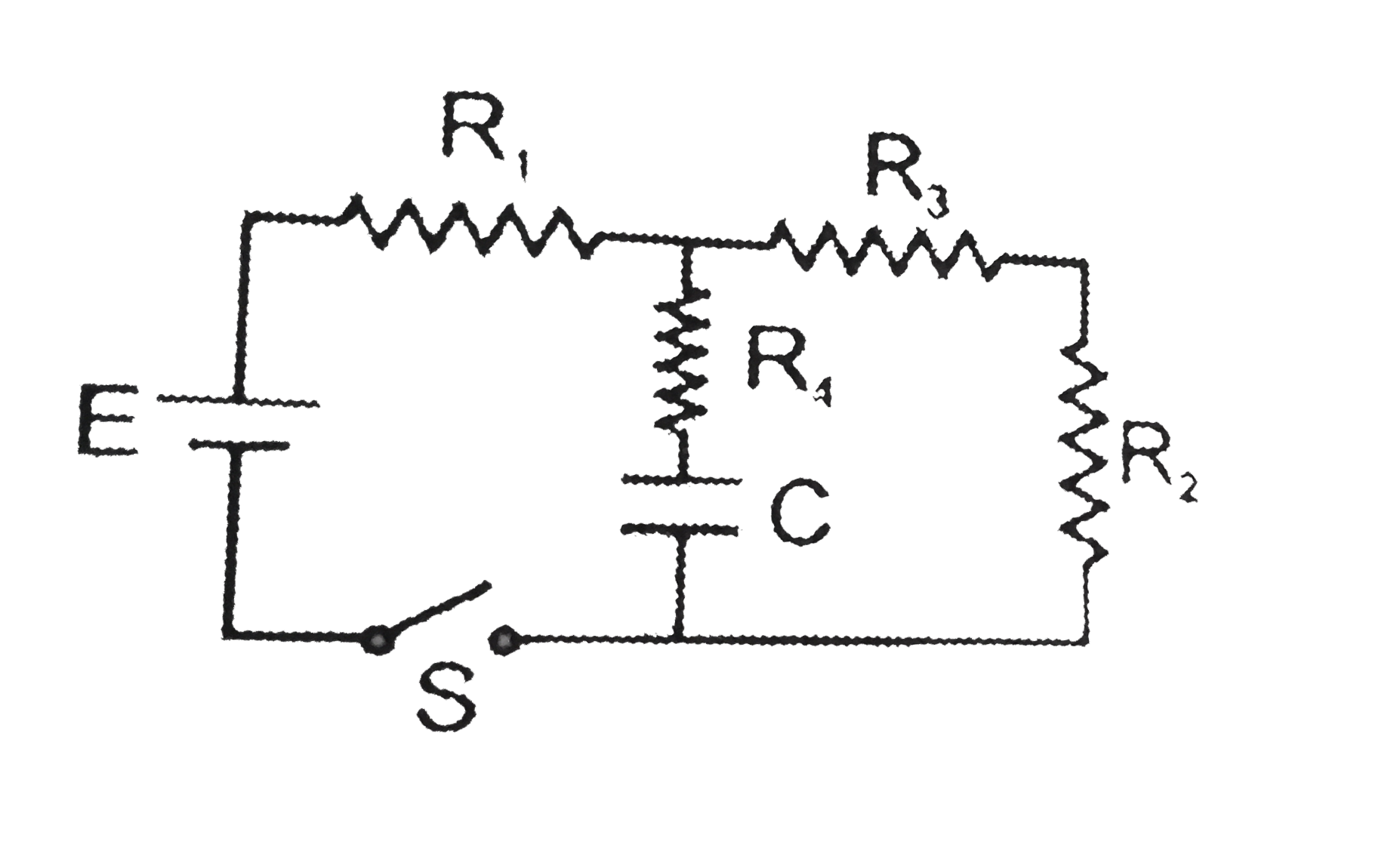
In the circuit shown in figure the switch S is closed at t = 0. A long time after closing the switch
 View Solution
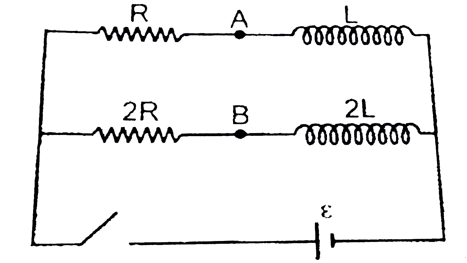
In given LR circuit the switch S is closed at time t=0 thenView SolutionConsider the circuit shwon in fig. The circuit is in steady state.
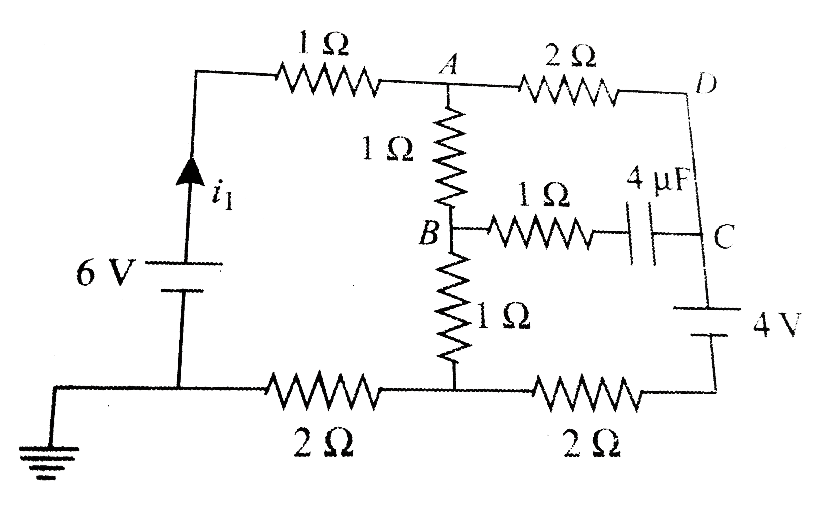
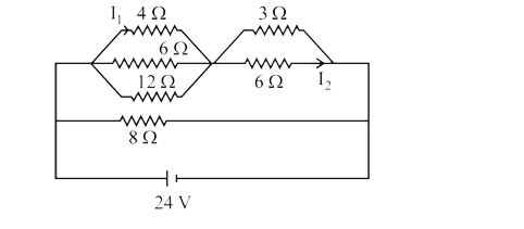
The value of i1 isView SolutionIn the circuit shown in fig., the value of I1+I2 is
 View Solution
In the circuit shown in fig., the value of I1+I2 is
 View Solution
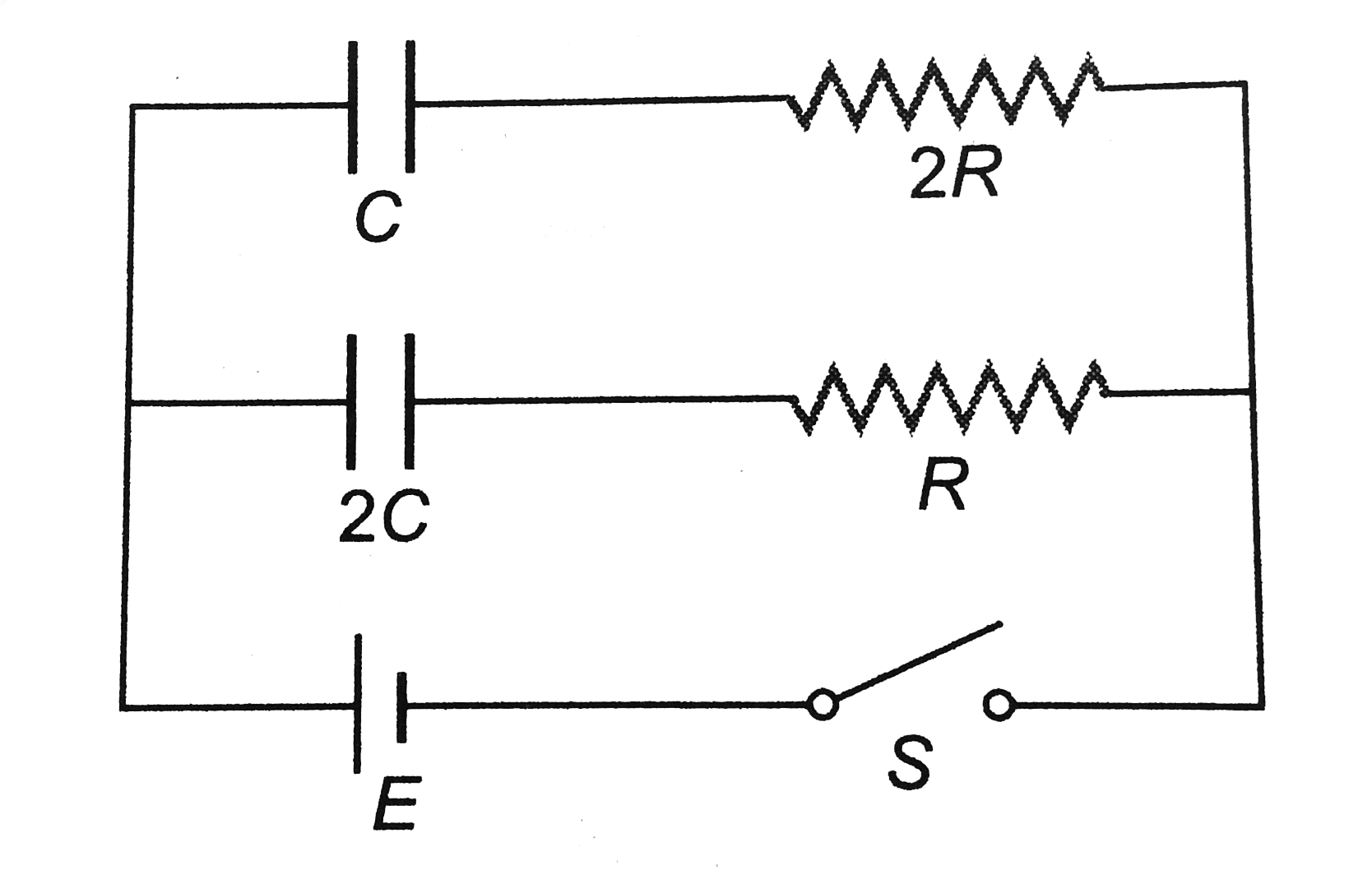
In the circuit shown in the figure, switch S is closed at time t=0. Select the correct statements.
 View Solution
