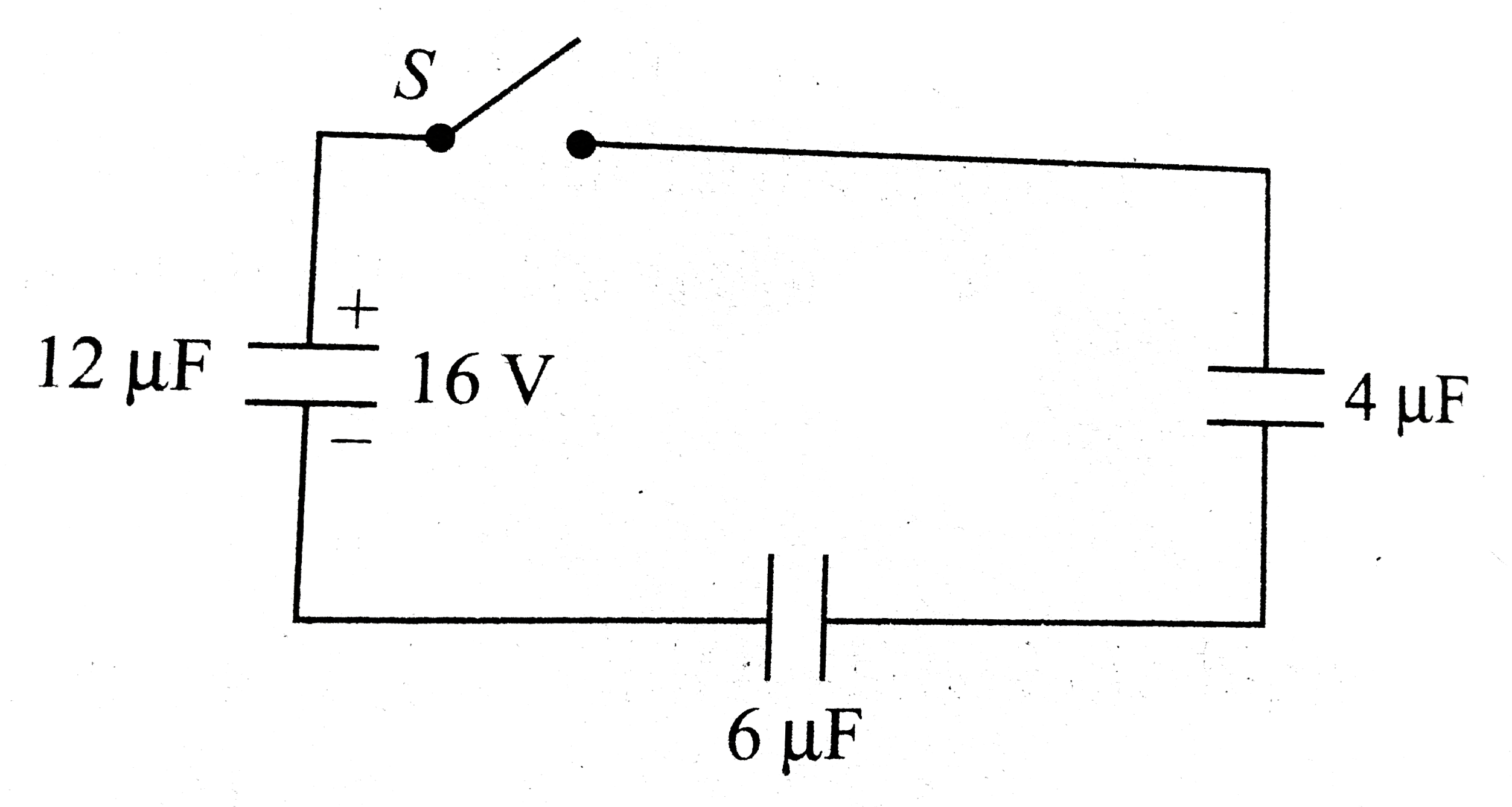
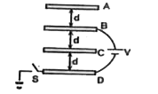
In the arrangement shown in, When the switch S is closed, find
 .
.
the final potential difference across the 12μF capacitor.
403V
203V
12V
24V
The correct Answer is:A
In the close loop,
q0−ΔqC1−ΔqC2−ΔqC2=0
 .
.
q0C1=Δq[1C1+1C2+1C3]
Δq=q0C1[1C1+1C2+1C3]=192[1+3+2)=32μC
Potential defferece across C1=ΔqC2=8V
Potential defferece across C1=(192−32)12=16012=403V.
Topper's Solved these Questions
- CAPACITOR AND CAPACITANCEBOOK - CENGAGE PHYSICS ENGLISHCHAPTER - CAPACITOR AND CAPACITANCEEXERCISE - Integer
5 Videos
- CAPACITOR AND CAPACITANCEBOOK - CENGAGE PHYSICS ENGLISHCHAPTER - CAPACITOR AND CAPACITANCEEXERCISE - Multile Correct
11 Videos
- ATOMIC PHYSICSBOOK - CENGAGE PHYSICS ENGLISHCHAPTER - ATOMIC PHYSICSEXERCISE - ddp.4.3
15 Videos
- CENGAGE PHYSICS DPPBOOK - CENGAGE PHYSICS ENGLISHCHAPTER - CENGAGE PHYSICS DPPEXERCISE - subjective type
51 Videos
Similar Questions
In the arrangement shown in , the switch S is find
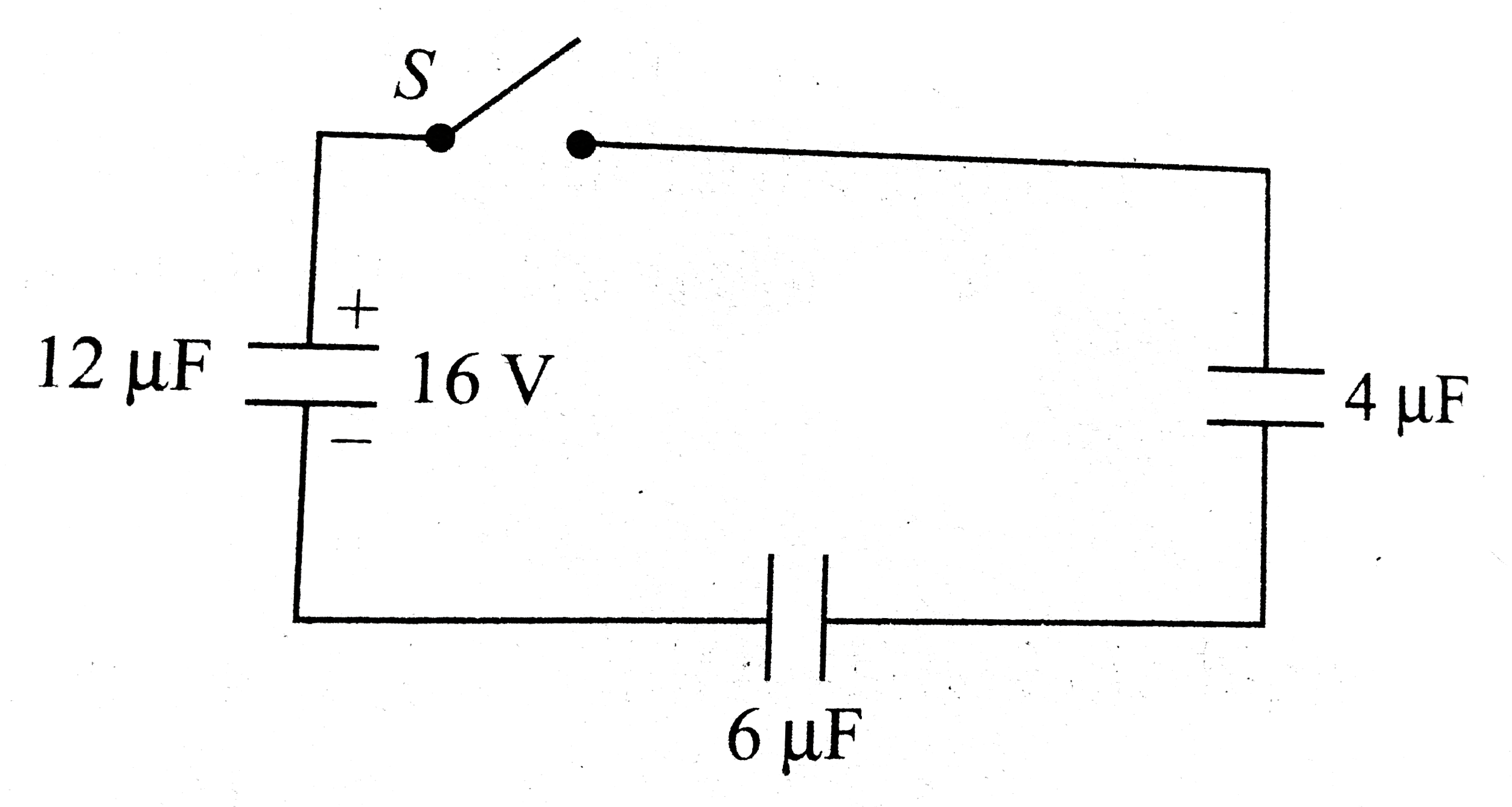 the final potential difference across the 4μF capacitor
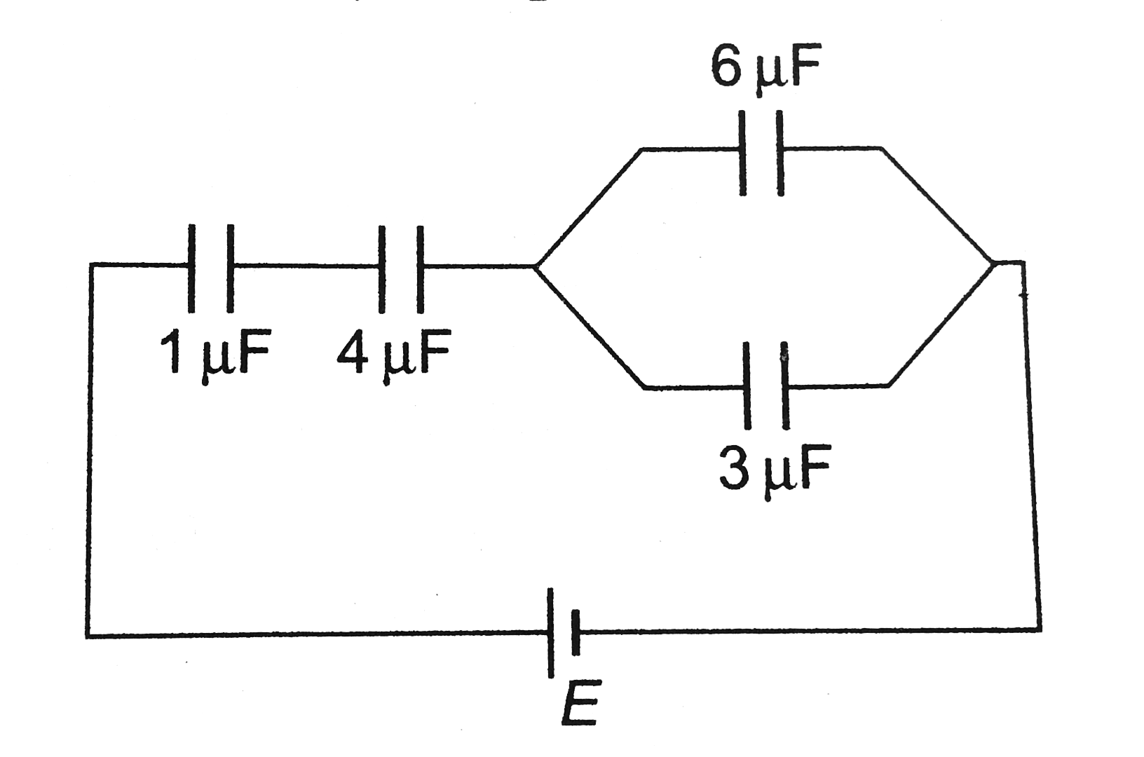
View Solutiongiven that potential differene across 1μF capacitor is 10V. Then,
View SolutionIn the arrangement shown in in the switch S is , find
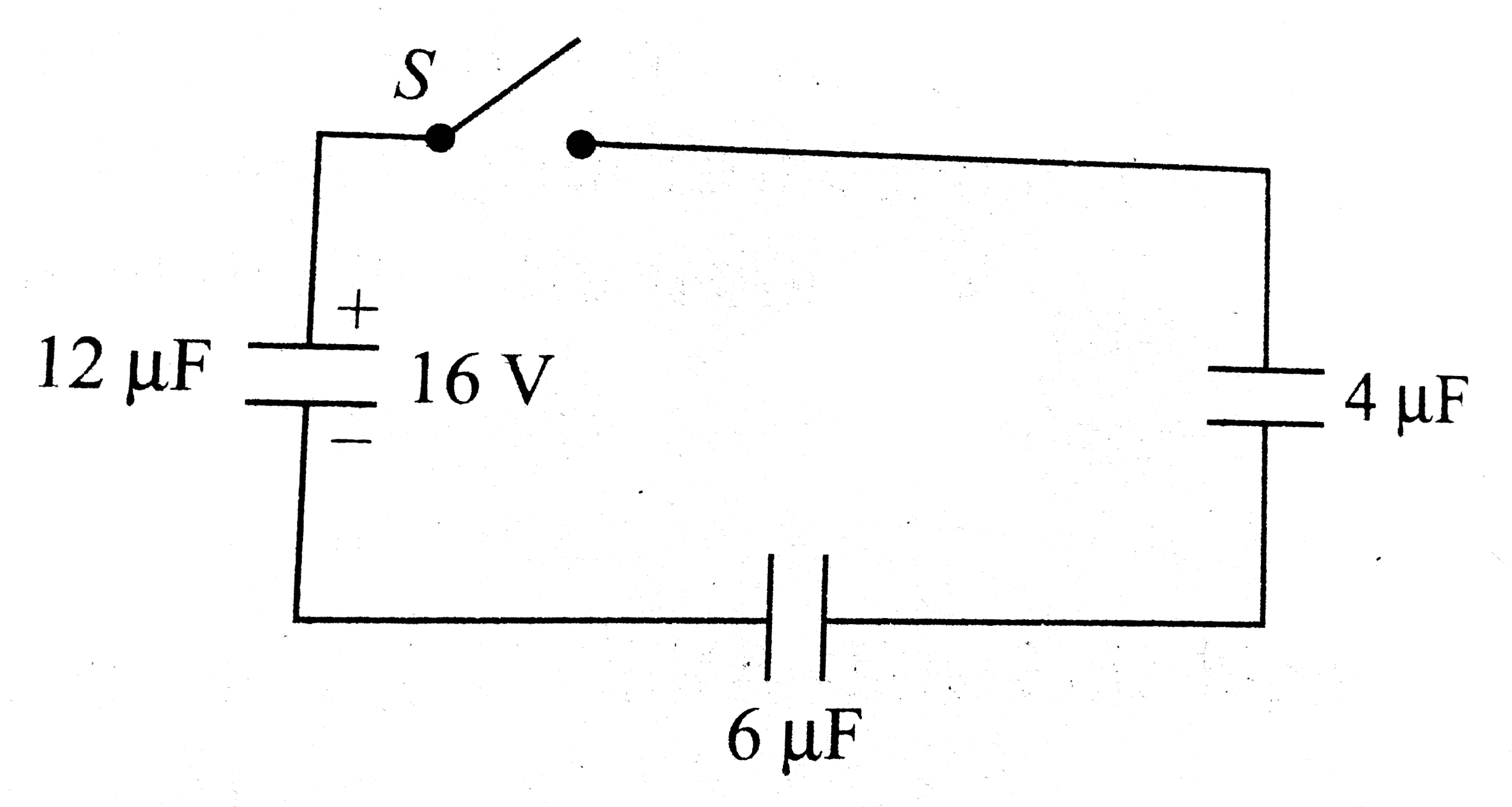
the final charge on the 6μF capacitor
View SolutionFind the charge flown when the switch S is closed.
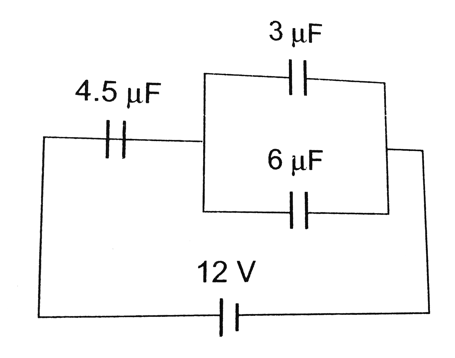
View SolutionIn the adjoning figure, the potential difference across the 4.5μF capacitor is

View SolutionIn the circuit shown in the figure, the potential difference across the 4.5μF capacitor is
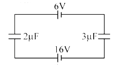
View SolutionWhat is the potential difference across 2μF capacitor in the circuit shown?
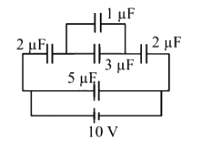
View SolutionThe ratio of potential differences between 1μFand5μF capacitors is
View SolutionThe potential drop across 7μF capacitor is 6V. Then

View SolutionIn the given circuit, the potential difference across the 6μF capacitor in steady state is

View Solution
