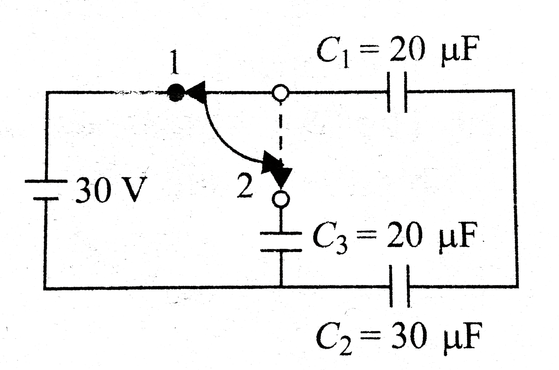
Condsider
 .
.
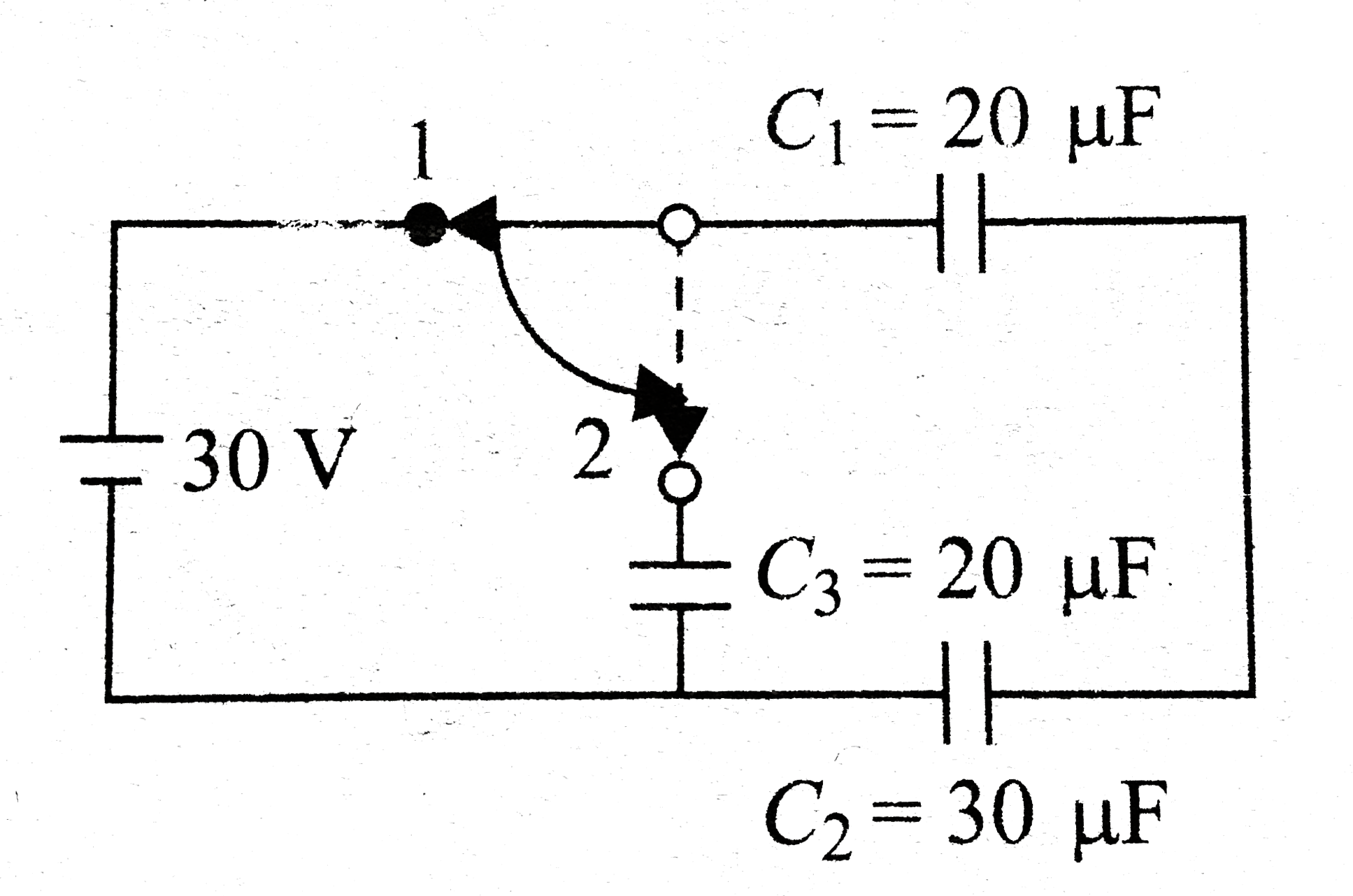
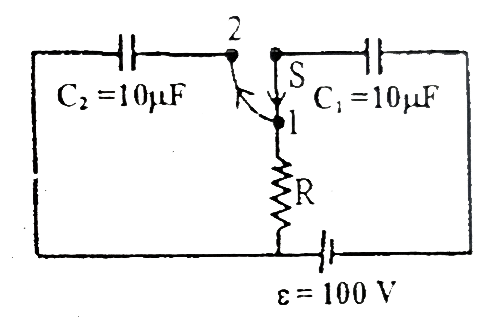
Now the switch is shifted to position 2. The charge appearing on capacitor C3 is
225μC
235μC
270μC
75μC
The correct Answer is:A
When switch is in position 1,
30=q20−q30=0 or q=360μC
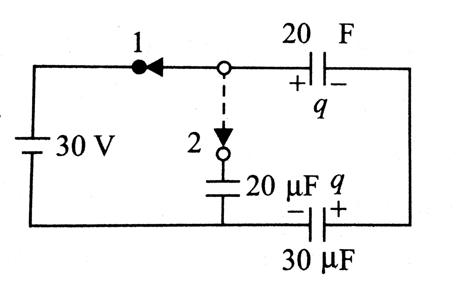
Now, the switch is in position2,
 .
.
LoopABCD,
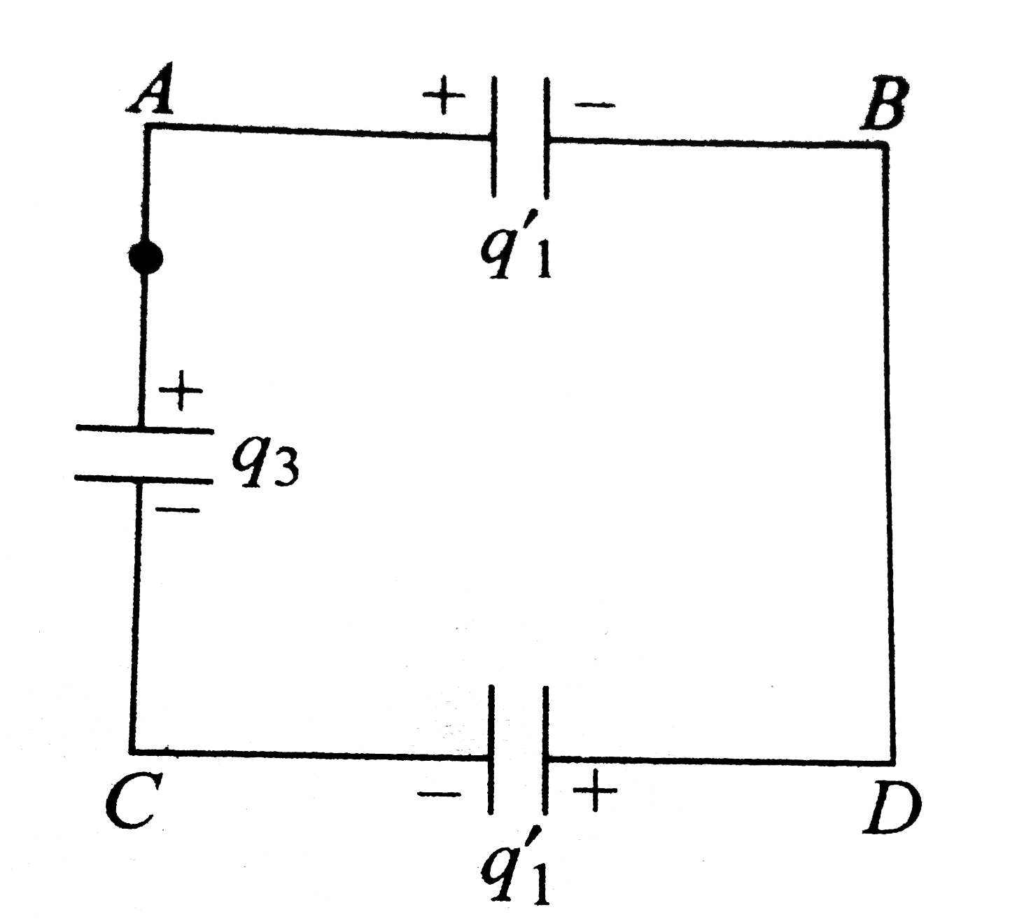
Q'120−Q'130+Q320=0
or −3q'1−2q1+3q3=0
or 5q'1=3q3 or q'1=35q3
8q35=360
q3=360×58=4502μC=225μC (ii)
q'1=35(4502)=135μC.
Topper's Solved these Questions
- CAPACITOR AND CAPACITANCEBOOK - CENGAGE PHYSICS ENGLISHCHAPTER - CAPACITOR AND CAPACITANCEEXERCISE - Integer
5 Videos
- CAPACITOR AND CAPACITANCEBOOK - CENGAGE PHYSICS ENGLISHCHAPTER - CAPACITOR AND CAPACITANCEEXERCISE - Multile Correct
11 Videos
- ATOMIC PHYSICSBOOK - CENGAGE PHYSICS ENGLISHCHAPTER - ATOMIC PHYSICSEXERCISE - ddp.4.3
15 Videos
- CENGAGE PHYSICS DPPBOOK - CENGAGE PHYSICS ENGLISHCHAPTER - CENGAGE PHYSICS DPPEXERCISE - subjective type
51 Videos
Similar Questions
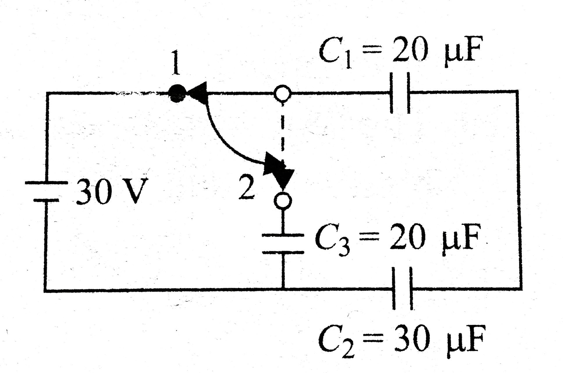
Condsider
 .
.
The charge on capacitor C1 is.
View SolutionCondsider
 .
.
In the circuit shown is the switch can be shifted to positions 1 and 2 The charge on capacitor C1 when the switch is at position 1 is.
View SolutionConsider
<imga≤ocr_imageload∈g=lazysrc=https://d10lpgp6xz60nq.cloudfront.net/physics_images/BMS_V03_C04_E01_141_Q01.pngwh=80%mx-autosty≤=background:white;>.<br>Thechar≥appear∈gisC_(2) is.
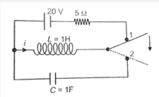
View SolutionIn the circuit shown, the switch has been in position 1 for a long time. Now the switch is shifted to position 2. If this instant is taken as t = 0, then at time t=π2
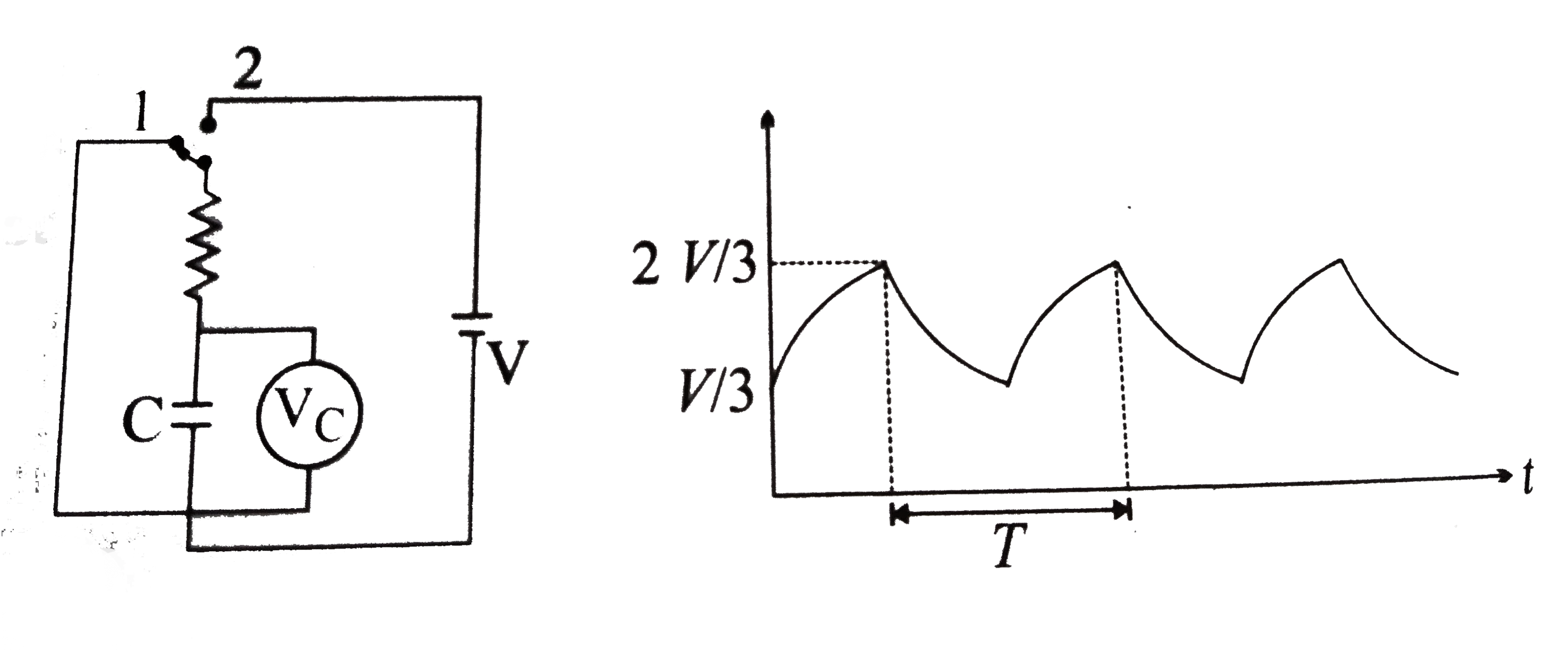
View SolutionVC is the ideal voltmeter in the figure. Resistance of the resistor shown is R. Initially the switch is in position 2 when charging of the capacitor starts. Initially the capacitor was uncharged. The switch in circuit shifts automatically from 2 to 1 when VC>2V/3 and goes back to 2 from 1 when VC<V/3. The ideal voltmeter reads voltage across capacitor as plotted. What is the period T of the wave from in terms of R and C ?
 ,
,
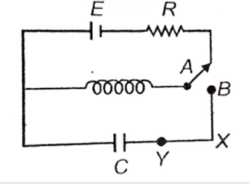
View SolutionSwitch is in position A for long time. At time t = 0 it is shifted to position B. Find the maximum charge that will accumulate on capacitor
View SolutionThe capacitor C shown in the figure is in steady state condition when switch is shifted from position 1 to position 2.The heat liberated in the process is
_PHY_E05_272_Q01.png)
View SolutionTwo identical capacitors are connected in the circuit shown. C2 is charged to 100V and switch S is shifted from position 1 to position 2. The negative terminal of C2 is connected with the positive terminal of C1. Find the work done by the battery. If the polarity of C2 were reversed, what work would have been done by the battery ?
View SolutionIn the following circuit, the switch S is closed at t = 0. The charge on the capacitor C1 as a function of time will be given by (Ceq=C1C2C1+C2)
View SolutionIn the circuit shown, switch S is placed in position 1 till the capacitor is charged to half of the maximum possible charge in this situation. Now, the switch S is placed in position 2. The maximum energy lost by the circuit after switch S is placed in position 2 is
View Solution
