Draw a sumbol for NOR gate and write its truth table.
Step-by-Step Solution:
Step 1: Draw the Symbol for NOR Gate
The symbol for a NOR gate consists of two inputs (A and B) and one output (Y). The shape is similar to an OR gate, but with a small circle (representing NOT) at the output.
____A−−−−|∣|NOR⊢−−YB−−−−⌊_⌋∣
Step 2: Write the Expression for the Output
The output Y of a NOR gate can be expressed in terms of its inputs A and B. The output is the negation of the OR operation on the inputs:
\( Y = \overline{A + B} \)
Step 3: Construct the Truth Table
Now, we will create a truth table that shows all possible combinations of inputs A and B and the corresponding output Y.
| A | B | A + B | Y = ¬(A + B) |
|---|---|-------|--------------|
| 0 | 0 | 0 | 1 |
| 0 | 1 | 1 | 0 |
| 1 | 0 | 1 | 0 |
| 1 | 1 | 1 | 0 |
Step 4: Finalize the Truth Table
From the truth table, we can summarize the output Y based on the values of A and B.
- When both A and B are 0, Y is 1.
- When A is 0 and B is 1, Y is 0.
- When A is 1 and B is 0, Y is 0.
- When both A and B are 1, Y is 0.
Final Truth Table:
| A | B | Y |
|---|---|---|
| 0 | 0 | 1 |
| 0 | 1 | 0 |
| 1 | 0 | 0 |
| 1 | 1 | 0 |
|---|---|-------|--------------|
| 0 | 0 | 0 | 1 |
| 0 | 1 | 1 | 0 |
| 1 | 0 | 1 | 0 |
| 1 | 1 | 1 | 0 |
- When A is 0 and B is 1, Y is 0.
- When A is 1 and B is 0, Y is 0.
- When both A and B are 1, Y is 0.
|---|---|---|
| 0 | 0 | 1 |
| 0 | 1 | 0 |
| 1 | 0 | 0 |
| 1 | 1 | 0 |
Similar Questions
Draw the symbol for AND gate and write its truth table.

View SolutionWhat is the symbol of a NOR gate? Write its truth table.
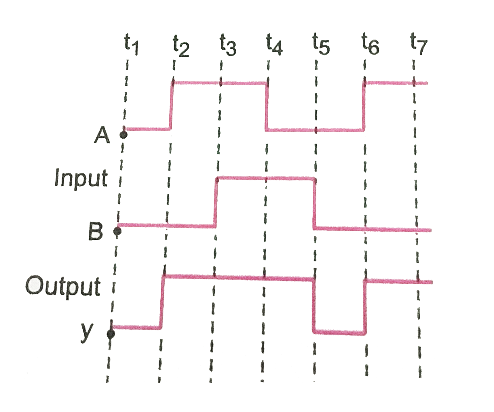
View SolutionThe following Fig. shows the input waveforms (A,B) and the output waveform (y) of a gate. Identify the gate and write its truth table.

View SolutionWhat is a NAND gate ? Write its truth table.
View SolutionThe figure shows the input weveforms A and B for 'AND' gate Draw the output waveform and write the truth table for this logic gate
 .
.
View SolutionThe Fig shown input waveforms A and B to a logic gate. Draw the output waveform for an OR gate. Write the truth table for this logic gate and draw its logic symbol.

View SolutionIt is required to design a (two -input) logic gate, using an appropriate number, of :
(a) NAND gates that gives a 'low' output only when both the inputs are 'low'.
(b) NOR gates that gives a 'high' output only when both the inputs are 'high'.
Draw the logic circuits for these two cases and write the truth table, corresponding to each of the two designs.
View SolutionShow how you will obtain an AND gate using only NOR gates. Draw the truth table for this arrangement of gates.
View Solution(a) In the figure given below the input waveform is converted into the output waveform by a device 'X'. Name the device and draw its circuit diagram.

(b) Identify the logic gate represented by the circuit as shown and write its truth table.

View SolutionThe output of a 2-input AND gate is fed to a NOT gate. Give the name of the combination and its logic symbol. Write down its truth table.
View Solution
