The output of a 2-input AND gate is fed to a NOT gate. Give the name of the combination and its logic symbol. Write down its truth table.
To solve the problem, we need to follow these steps:
Step 1: Identify the Logic Gates
The problem states that the output of a 2-input AND gate is fed to a NOT gate.
Step 2: Define the Logic Gates
1. AND Gate: The output of an AND gate is true (1) only if both inputs are true (1).
2. NOT Gate: The output of a NOT gate is the inverse of the input; if the input is true (1), the output is false (0), and vice versa.
Step 3: Determine the Combination Name
The combination of an AND gate followed by a NOT gate is called a NAND gate (NOT AND).
Step 4: Draw the Logic Symbol
The logic symbol for a NAND gate consists of the symbol for an AND gate with a small circle (bubble) at the output to indicate the NOT operation. The symbol looks like this:
A−−−−|&⊢−−o−−−−YB−−−−|∣∣
Step 5: Write the Output Expression
Let:
- A = First input
- B = Second input
- X = Output of the AND gate = A AND B = A · B
- Y = Output of the NOT gate = NOT X = (A · B)'
Thus, the output expression is:
\( Y = (A \cdot B)' \)
Step 6: Create the Truth Table
Now, we will create the truth table for the NAND gate.
| A | B | A · B | Y = (A · B)' |
|---|---|-------|--------------|
| 0 | 0 | 0 | 1 |
| 0 | 1 | 0 | 1 |
| 1 | 0 | 0 | 1 |
| 1 | 1 | 1 | 0 |
Final Summary
- Combination Name: NAND gate
- Logic Symbol: (as described above)
- Truth Table: (as shown above)
The problem states that the output of a 2-input AND gate is fed to a NOT gate.
1. AND Gate: The output of an AND gate is true (1) only if both inputs are true (1).
2. NOT Gate: The output of a NOT gate is the inverse of the input; if the input is true (1), the output is false (0), and vice versa.
The combination of an AND gate followed by a NOT gate is called a NAND gate (NOT AND).
The logic symbol for a NAND gate consists of the symbol for an AND gate with a small circle (bubble) at the output to indicate the NOT operation. The symbol looks like this:
Let:
- A = First input
- B = Second input
- X = Output of the AND gate = A AND B = A · B
- Y = Output of the NOT gate = NOT X = (A · B)'
\( Y = (A \cdot B)' \)
Now, we will create the truth table for the NAND gate.
|---|---|-------|--------------|
| 0 | 0 | 0 | 1 |
| 0 | 1 | 0 | 1 |
| 1 | 0 | 0 | 1 |
| 1 | 1 | 1 | 0 |
- Combination Name: NAND gate
- Logic Symbol: (as described above)
- Truth Table: (as shown above)
Topper's Solved these Questions
- XII BOARDSBOOK - XII BOARD PREVIOUS YEAR PAPER ENGLISHCHAPTER - XII BOARDSEXERCISE - SET III
7 Videos
- XII BOARDSBOOK - XII BOARD PREVIOUS YEAR PAPER ENGLISHCHAPTER - XII BOARDSEXERCISE - SET-III
22 Videos
- XII BOARDSBOOK - XII BOARD PREVIOUS YEAR PAPER ENGLISHCHAPTER - XII BOARDSEXERCISE - SET I
54 Videos
- SAMPLE PAPER 2019BOOK - XII BOARD PREVIOUS YEAR PAPER ENGLISHCHAPTER - SAMPLE PAPER 2019EXERCISE - SECTION D
6 Videos
Similar Questions
What is the symbol of a NOR gate? Write its truth table.
View SolutionWhat is a NAND gate ? Write its truth table.
View SolutionDraw the symbol for AND gate and write its truth table.

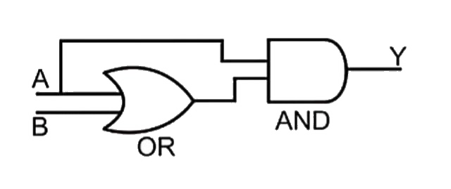
View SolutionThe output Y of the combination of logic gates shown is equal to
View SolutionThe output of an OR gate is connected to both the inputs of a NAND gate. The combination will serve as a
View SolutionDraw a sumbol for NOR gate and write its truth table.
View Solution(i) Sketch the output waveform from an AND gate for the inputs A and B shown in the figure.
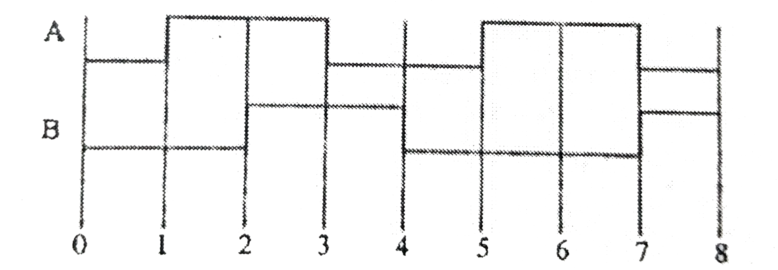
(ii) If the output of the above AND gate is fed to a NOT gate, name the gate of the combination so formed.
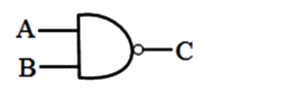
View SolutionFor given logic gate truth table is
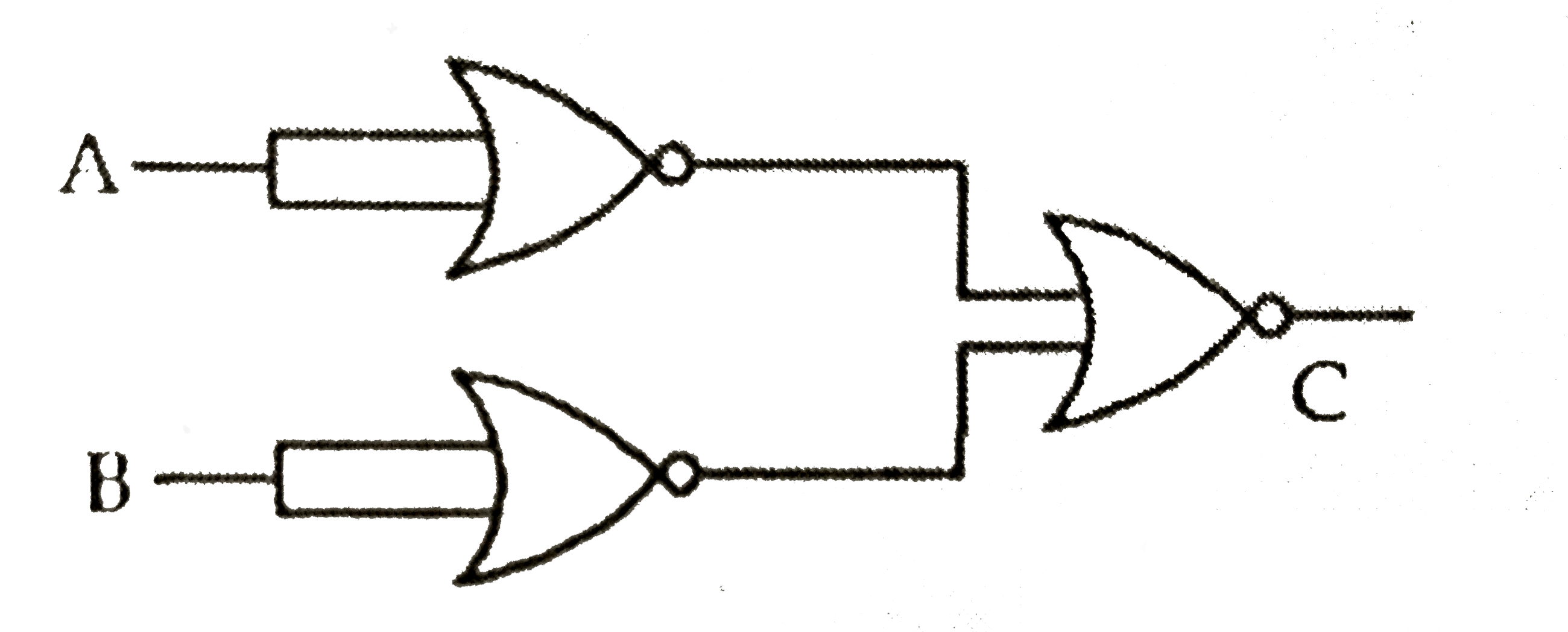
View SolutionWrite the truth table for the combination of the gates shown in the figure.
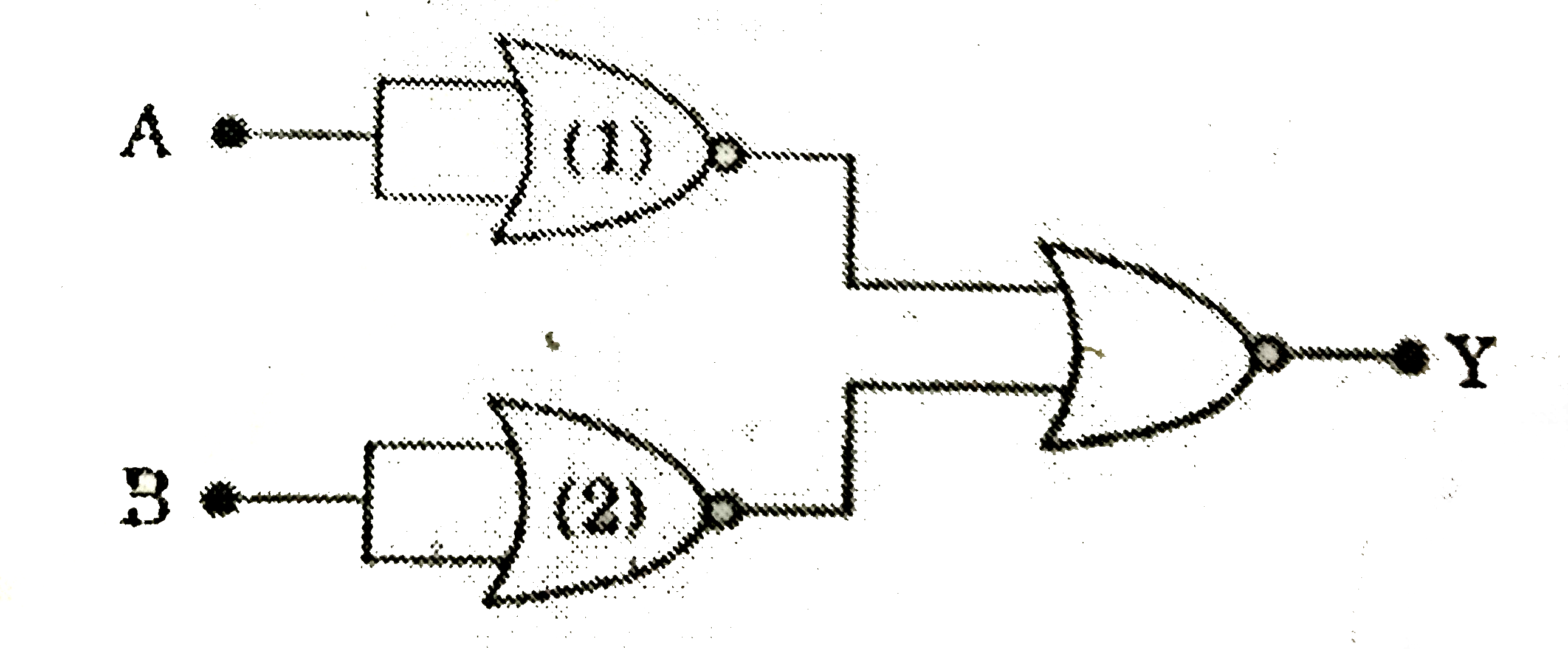
View SolutionThe inputs A and B are inverted by using two NOT gates and their outputs are fed to the NOR gate as shown:
Analyse the action of the gates (1) and (2) and identify the logic gate of the complete circuit so obtained. Give its symbol and the truth table.
View Solution
