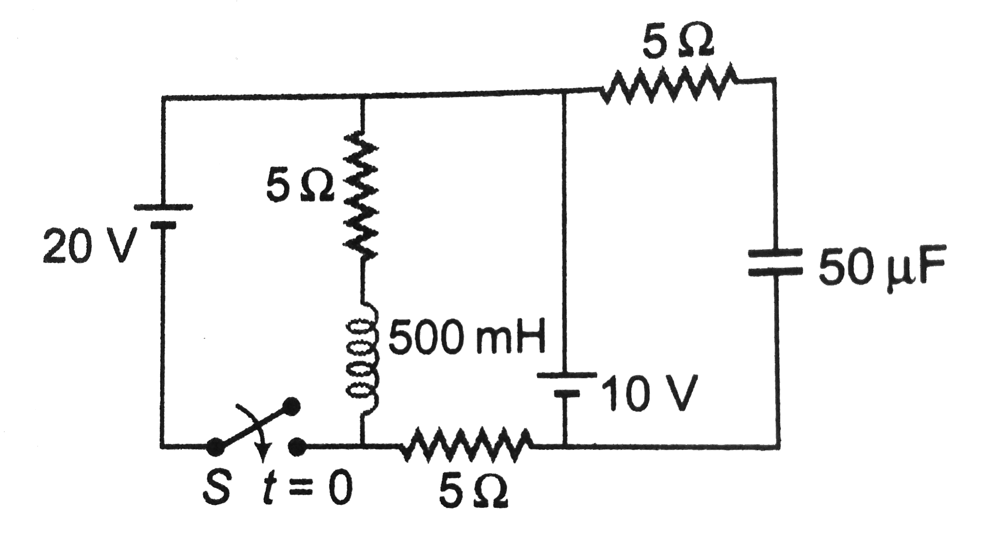
Switch S is closed t=0, in the circuit shown. The change in flux in the inductor (L=500mH) from t=0 to an instant when it reaches steady state is
2WB
1.5Wb
0Wb
None of these
The correct Answer is:B
Initial current =1010=1A
:. ϕi=L(Ii)=500mWb=0.5Wb
Final current =205=4A
ϕf=L(If)=(0.5)×4=2Wb
∴△ϕ=1.5Wb
Topper's Solved these Questions
- ELECTROMAGNETIC INDUCTIONBOOK - DC PANDEY ENGLISHCHAPTER - ELECTROMAGNETIC INDUCTIONEXERCISE - Level 2 More Than One Correct
10 Videos
- ELECTROMAGNETIC INDUCTIONBOOK - DC PANDEY ENGLISHCHAPTER - ELECTROMAGNETIC INDUCTIONEXERCISE - Level 2 Comprehension Based
13 Videos
- ELECTROMAGNETIC INDUCTIONBOOK - DC PANDEY ENGLISHCHAPTER - ELECTROMAGNETIC INDUCTIONEXERCISE - Level 1 Subjective
21 Videos
- CURRENT ELECTRICITYBOOK - DC PANDEY ENGLISHCHAPTER - CURRENT ELECTRICITYEXERCISE - Medical entrances gallery
97 Videos
- ELECTROMAGNETIC WAVESBOOK - DC PANDEY ENGLISHCHAPTER - ELECTROMAGNETIC WAVESEXERCISE - Sec C
22 Videos
Similar Questions
The switch S is closed in the circuit shown at time t=0 . The current in the resistor at t=0 and t=∞ are respectively .
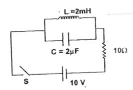
View SolutionSwitch is closed at t=0 then the current in the circuit at t=L2R is
_PHY_E06_157_Q01.png)
View SolutionSwitch S is cloesd in the circuit at time t=0. Find the current through the capacitor and the inductor at any time t
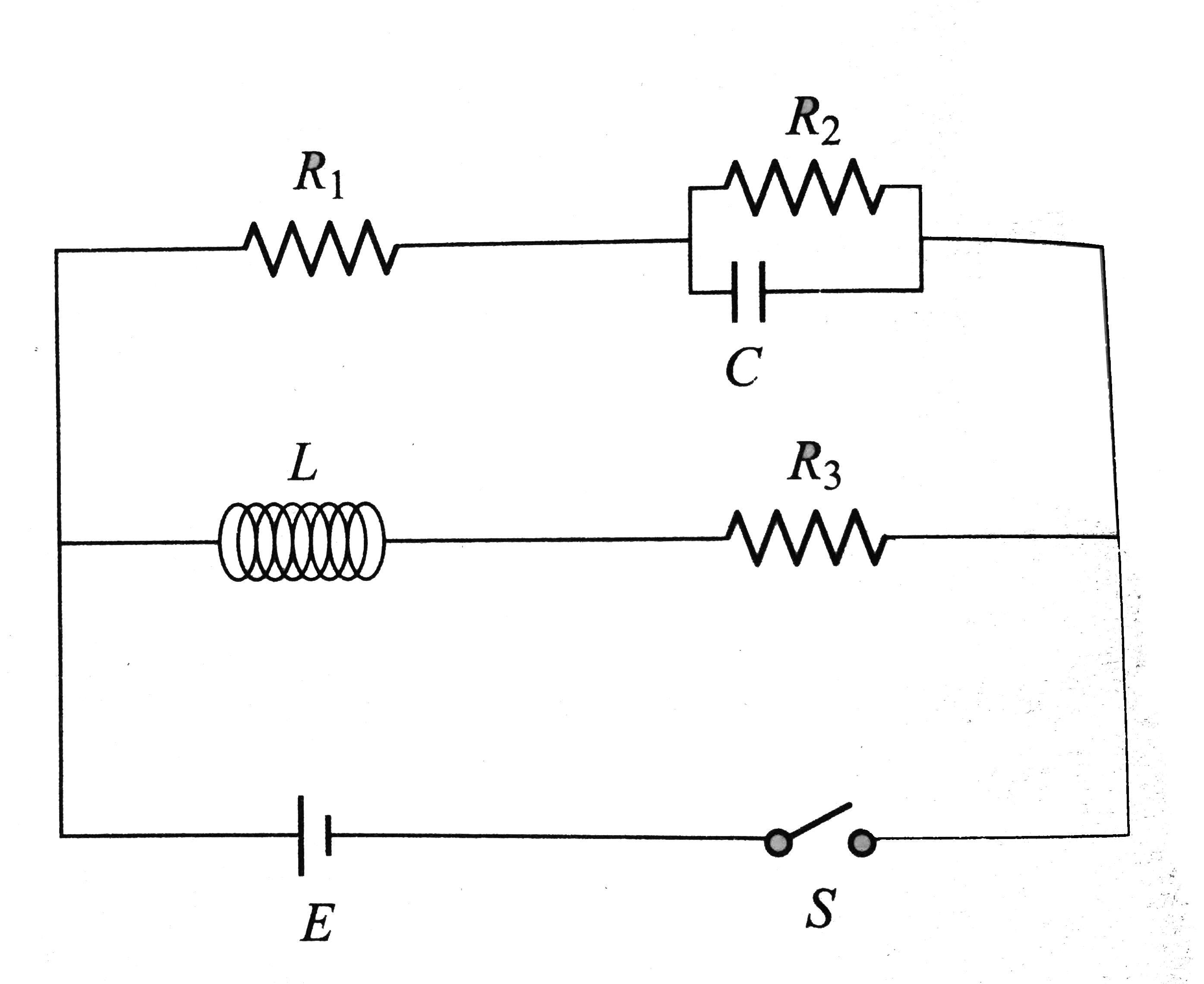
View SolutionIn the circuit as shown in the figure, switch S is added at t=0. Then:
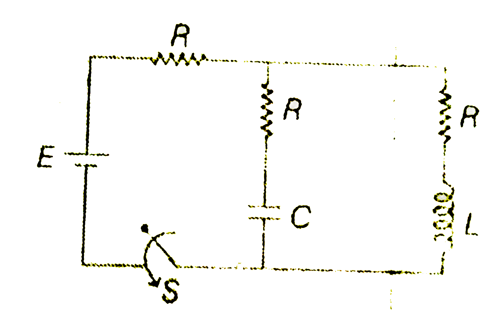
View SolutionIn the circuit shown, the switch 'S' is closed at t=0. Then the current through the battery steady state reached is
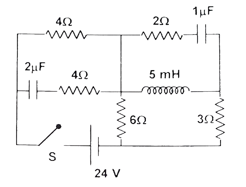
View SolutionIn the circuit diagram shown in figure, initially switch S is opened and the circuit is in steady state. At time t=0, the switch S is closed and the new steady state is reached after some time. Choose the correct option(s)
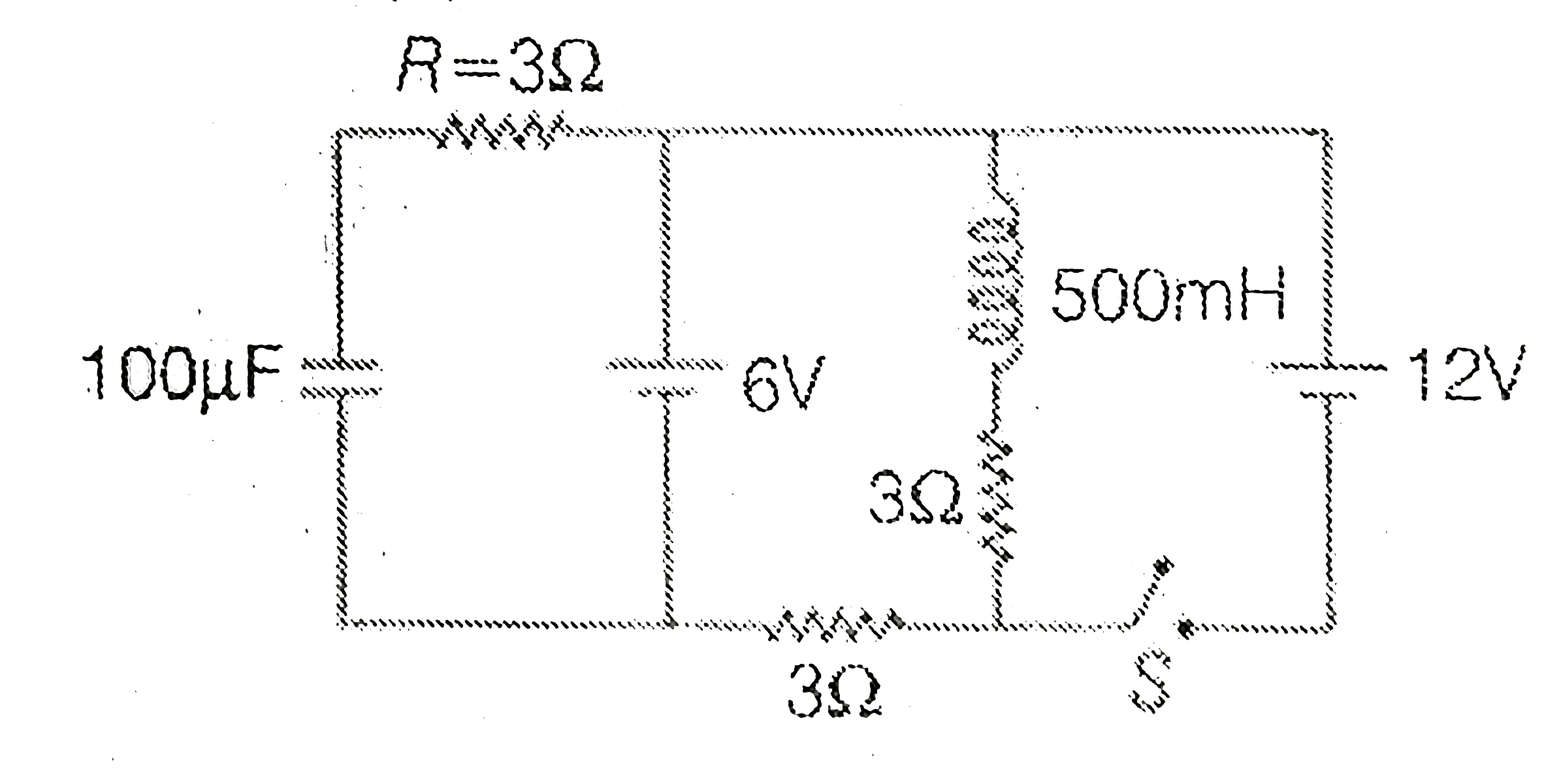
View SolutionIn the circuit shown in figure, the switch S is closed at t=0. If VL is the voltge induced across the inductor and i is the instantaneous current, the correct variation of VL versus is given by
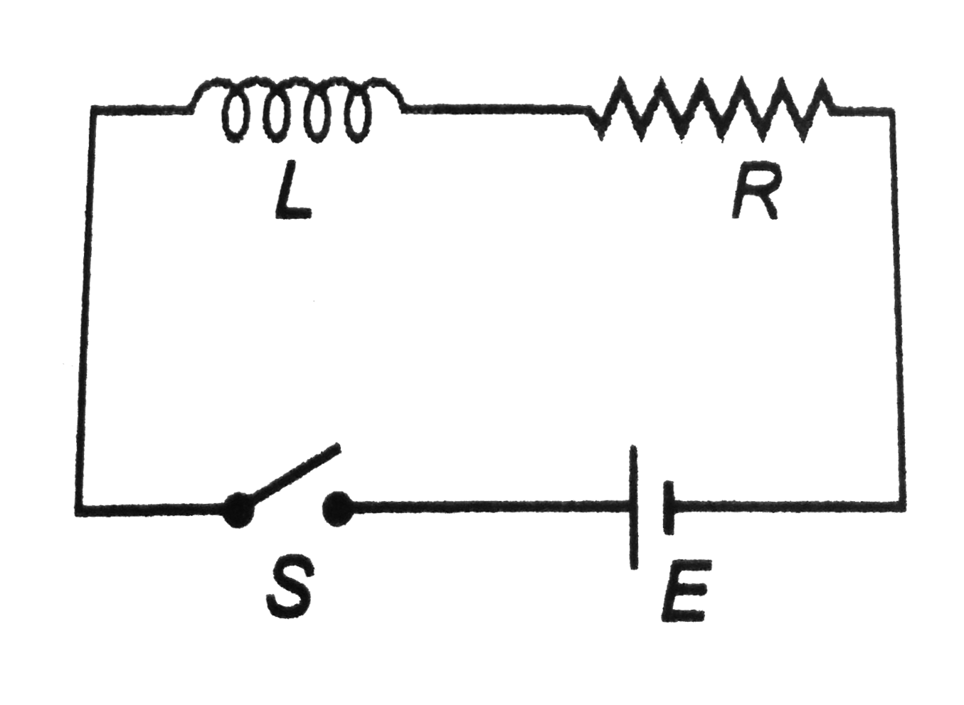
View SolutionIn the circuit shown in figure switch S is closed at time t=0, which statement is true after one time constant of L-R circuit?
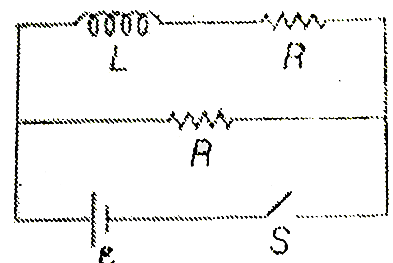
View SolutionIn the circuit shown in the figure, switch S is closed at time t=0. Select the correct statements.
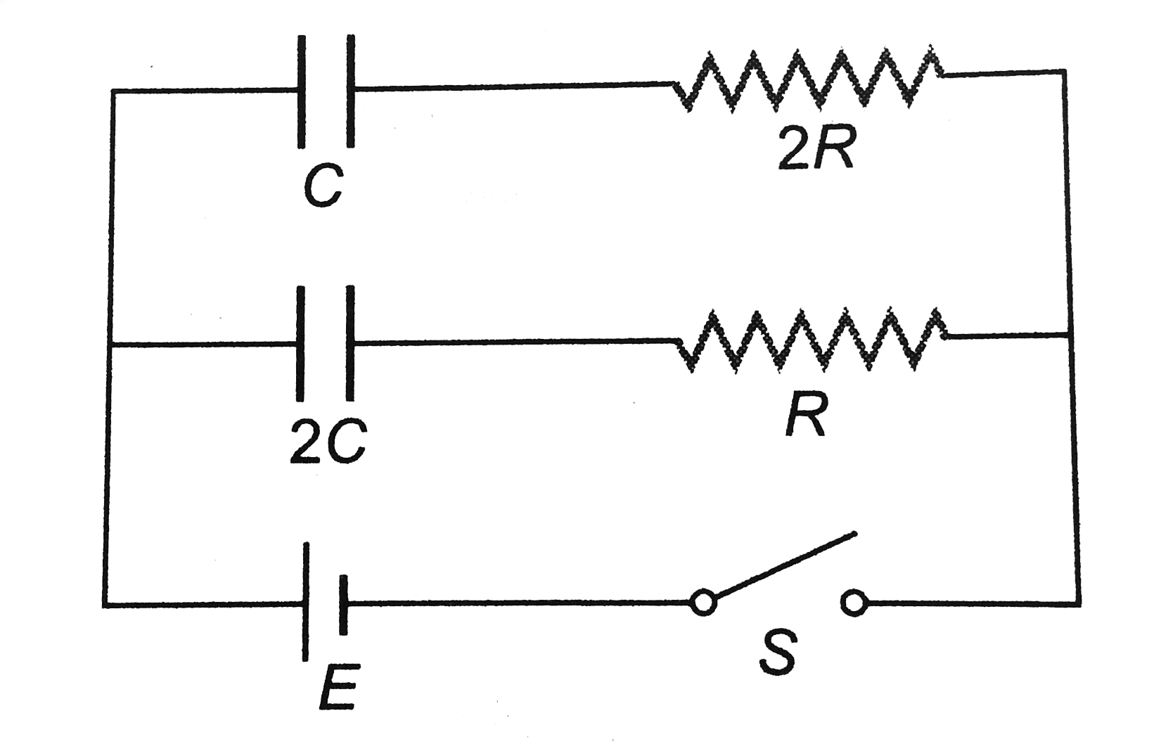
View SolutionIn the circuit shown in the figure, switch S is closed at time t=0. Select the correct statements.

View Solution
