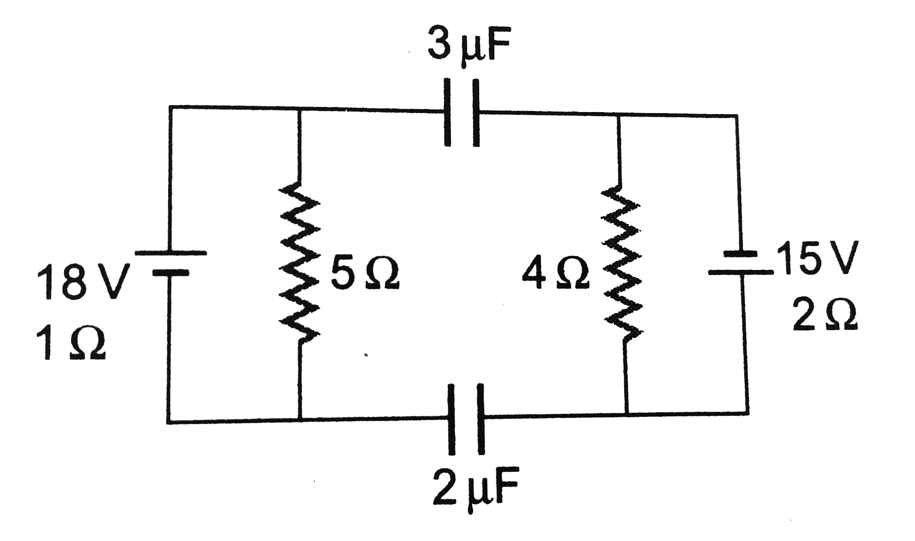
Two cellls, two resistance and two capacitors are connected as shown in figure. The charge on 2μF capacitors is
30μC
20μC
25μC
48μC
The correct Answer is:A
Applying Kirchoff's loop law in outermost loop, we have 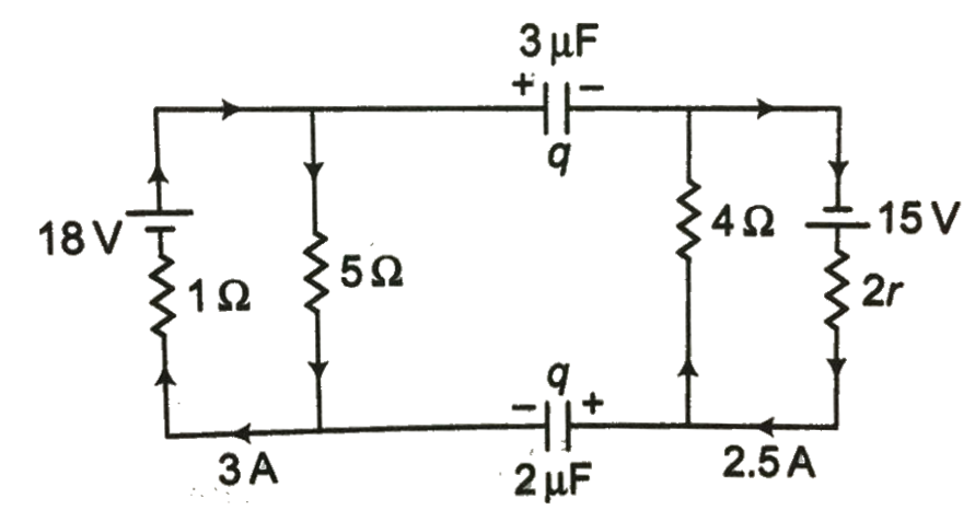
−q3+15−2×2.5−q2−3×1+18=0
solving this equation we get
Topper's Solved these Questions
- CAPACITORSBOOK - DC PANDEY ENGLISHCHAPTER - CAPACITORSEXERCISE - OBJECTIVE_TYPE
1 Videos
- CAPACITORSBOOK - DC PANDEY ENGLISHCHAPTER - CAPACITORSEXERCISE - OBJECTIVE_TYPE
1 Videos
- ATOMSBOOK - DC PANDEY ENGLISHCHAPTER - ATOMSEXERCISE - MEDICAL ENTRANCES GALLERY
42 Videos
- COMMUNICATION SYSTEMBOOK - DC PANDEY ENGLISHCHAPTER - COMMUNICATION SYSTEMEXERCISE - Subjective
11 Videos
Similar Questions
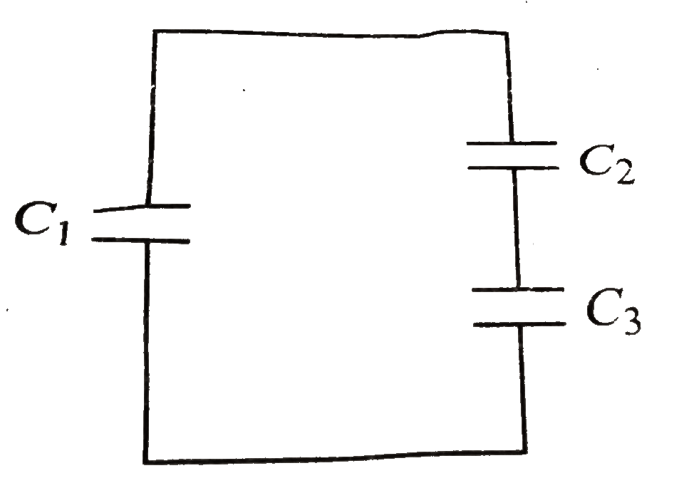
Capacitor C1 is connected to a battery and charged till the magnitude of the charge on each plate is q0. Then, the battery is disconnected and C1 is connected to two other uncharged capacitors C2andC3 as shown in figure. Final charges on the capacitors (q1,q2andq3) are related by .
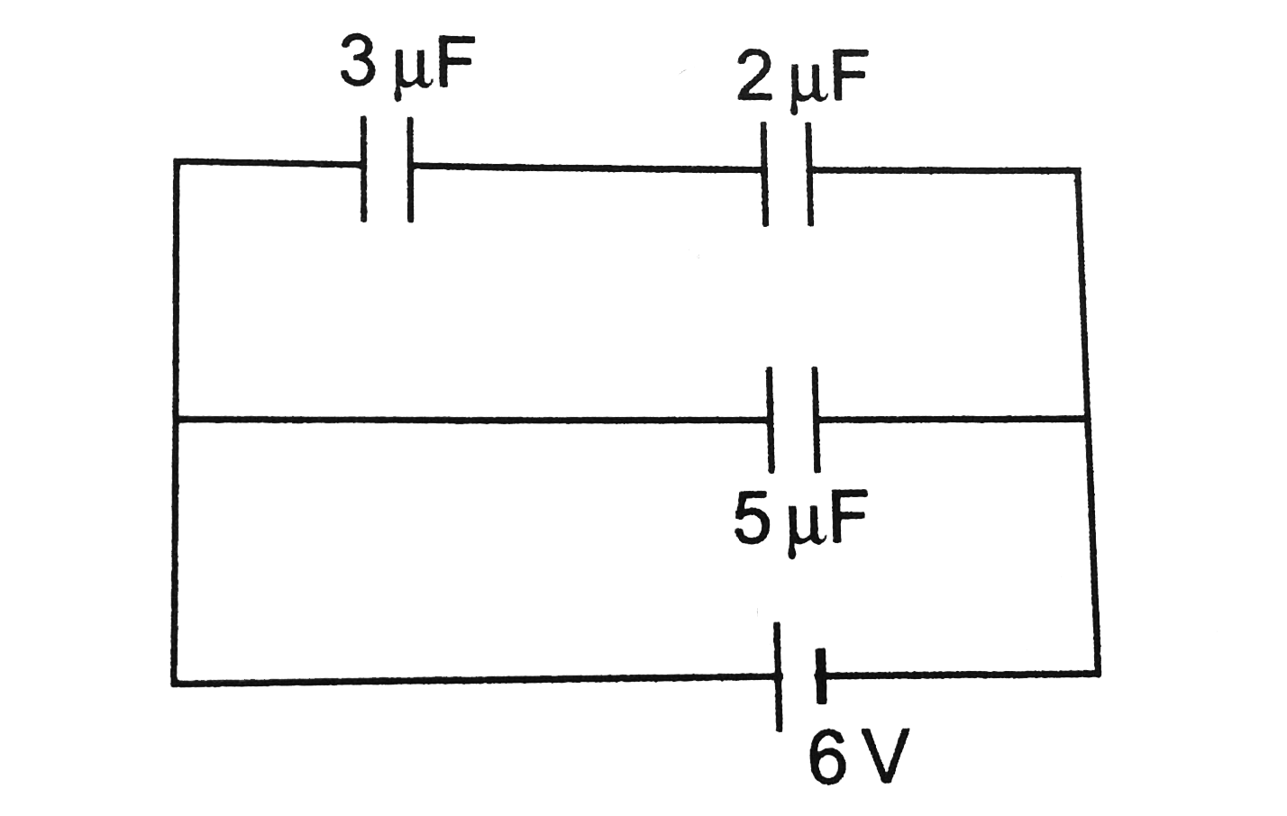
View SolutionIn the circuit shown in figure, the ratio of charge on 5μF and 2μF capacitor is
View SolutionTwo capacitors of 2μF and 3μF are charged to 150V and 120V, respectively. The plates of capacitor are connected as shown in the figure. An uncharged capacitor of capacity 1.5μF falls to the free end of the wire. Then
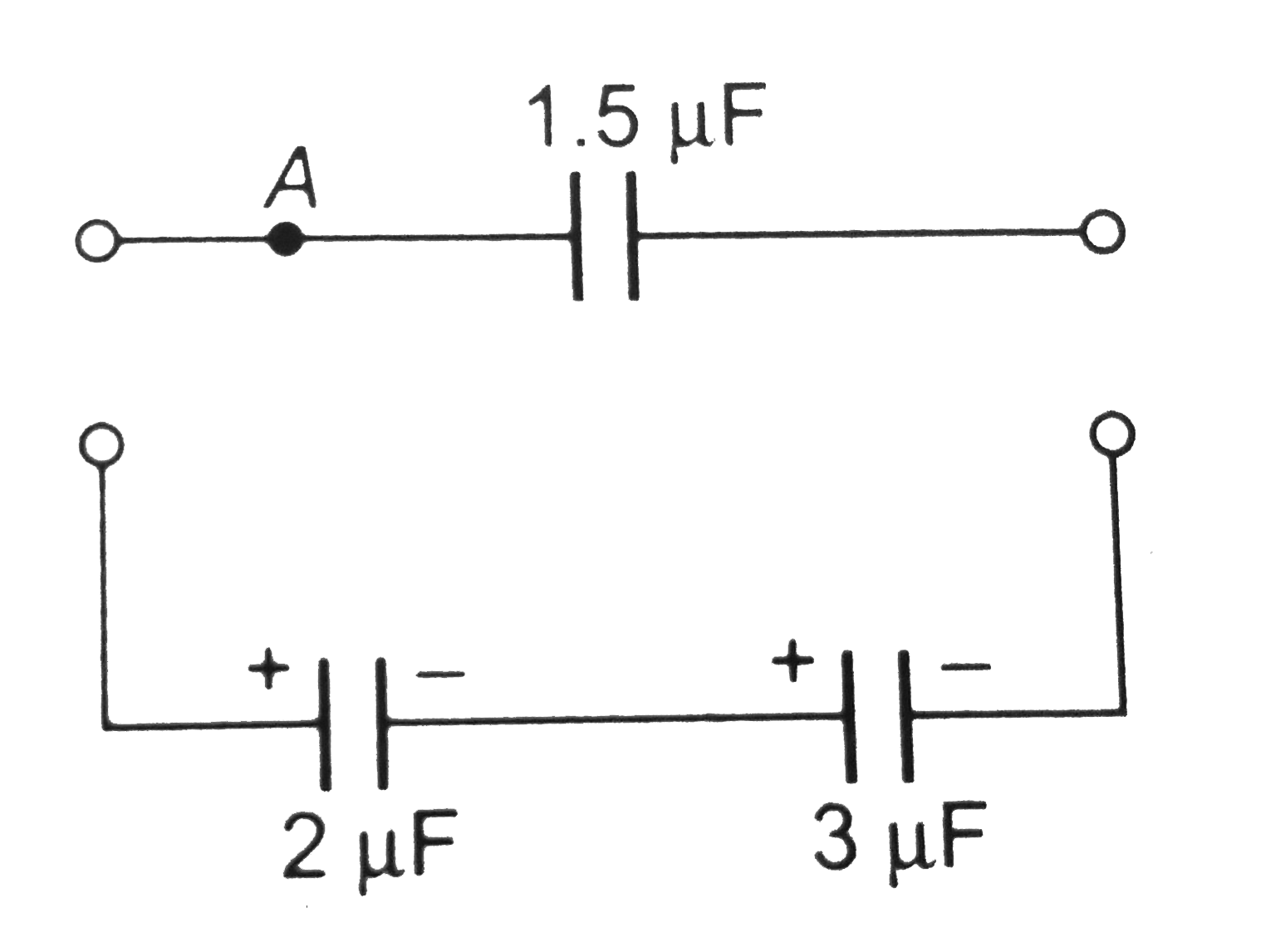
View SolutionTwo capacitors of 2μF and 3μF are charged to 150V and 120V, respectively. The plates of capacitor are connected as shown in the figure. An uncharged capacitor of capacity 1.5μF falls to the free end of the wire. Then

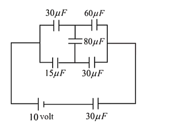
View SolutionIn the circuit shown below, the charge on the 60μF capacitor is
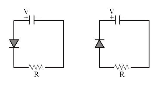
View SolutionTwo identical capacitors A and B are charged to the same potential V and are connected in two circuits at t = 0 as shown in figure. The charge of the capacitors at a time t = CR are respectively -
View SolutionIn the circuit shown in the figure, in steady state:
The charge on 5μF capacitor is
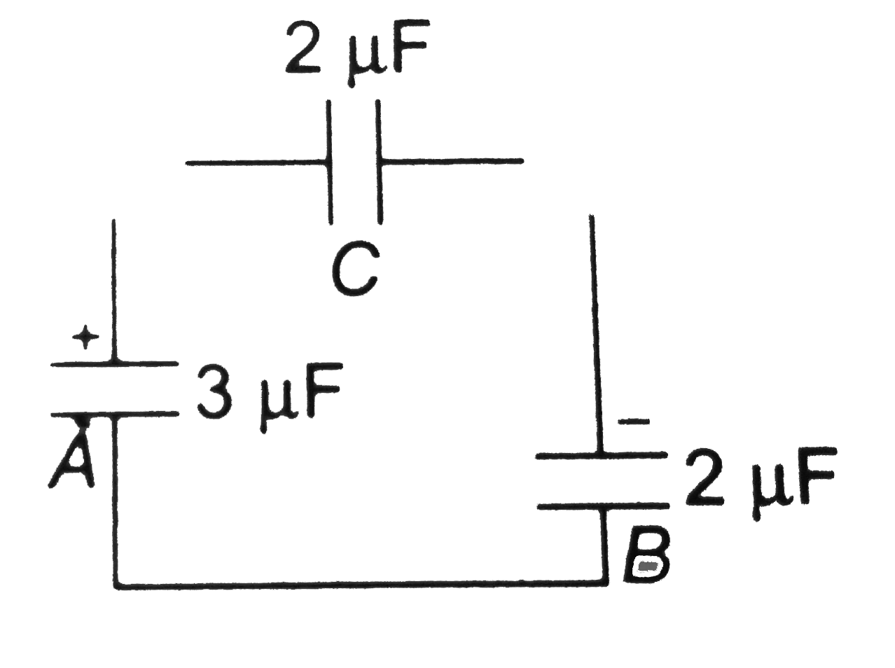
View SolutionTwo capacitors A and B with capacities 3μF and 2μF are charged to a potential difference of 100V and 180V, respectively. The plates of the capacitors are connected as show in figure with one wire of each capacitor free. The upper plate of A is positive and that of B is negastive. An uncharged 2μF capcitor C with lead wires falls on the free ends to complete the circuit. Calculate
a. the final charge on the three capacitors.
b. the amount of electrostatic energy stored in the system before and after completion of the circuit.
View SolutionSeveral capacitors are connected as shown in. If the charge on the 5μF capacitor is 120μC, the potential between points A and D is
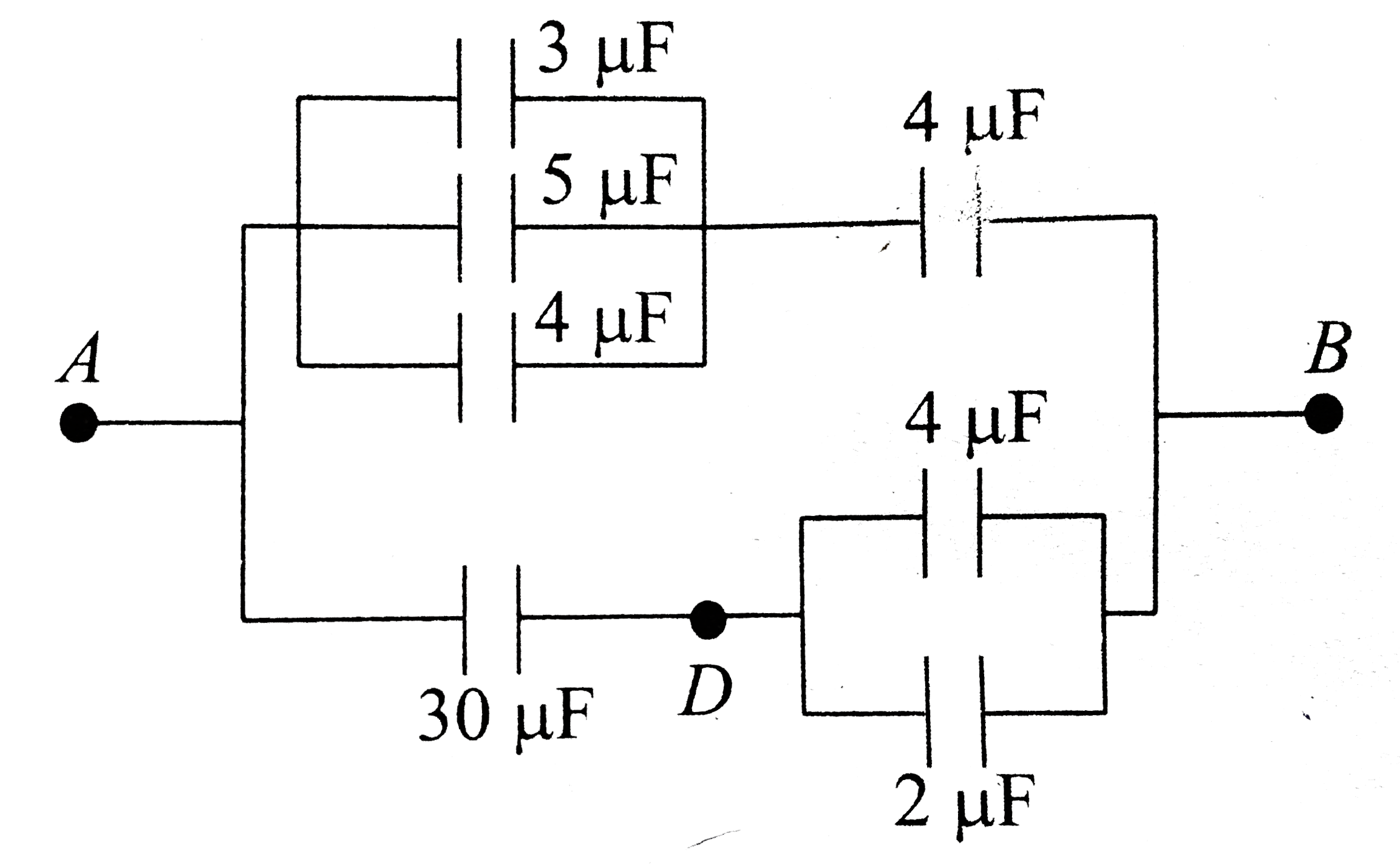 .
.
View SolutionSix identical capacitors are connected as shown in figure. Capacitance of each capacitors is 5μF The effective capacitance between point A and B is
View Solution

