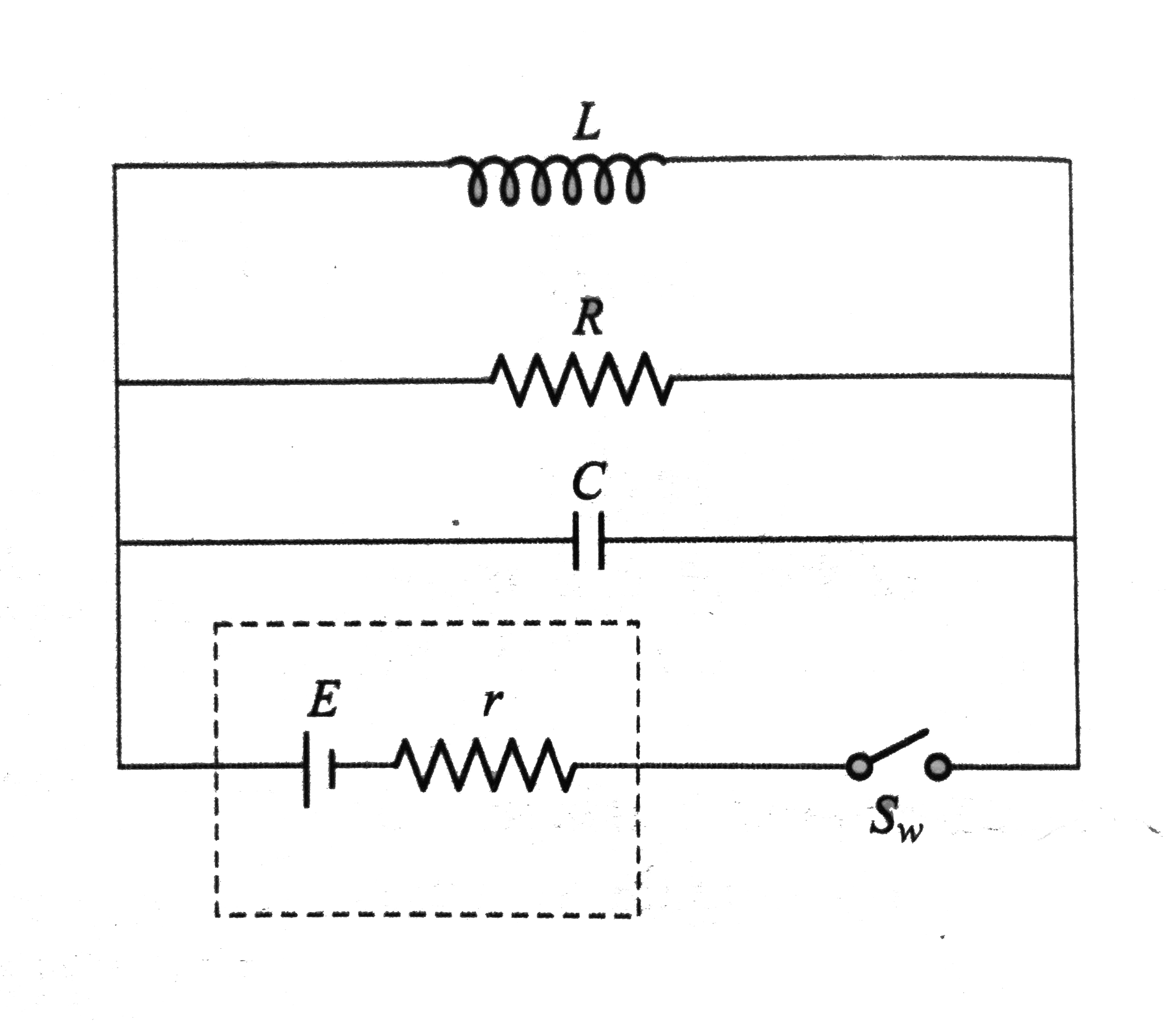
A pure inductor L, a capactior C and a resistance R are connected across a battery of emf E and internal resistance r as shows in Fig. Switch SW is closed at t=0, select the correct altermative (S).

Current through resistance R is zero all the time.
Current through resistance R is zero at t = 0 and t→∞.
Maximum charge stored in the capacitor is Cε.
Maximum energy stored in the inductor is equal to the maximum energy stored in the capacitor.
The correct Answer is:B
Step by step video, text & image solution for A pure inductor L, a capactior C and a resistance R are connected across a battery of emf E and internal resistance r as shows in Fig. Switch S_(W) is closed at t = 0, select the correct altermative (S). by Physics experts to help you in doubts & scoring excellent marks in Class 12 exams.
Updated on:21/07/2023Topper's Solved these Questions
- PRACTICE PAPPERBook:NCERT FINGERTPS ENGLISHChapter:PRACTICE PAPPERExercise:Practice Paper 1
Explore 50 Videos
- PRACTICE PAPPERBook:NCERT FINGERTPS ENGLISHChapter:PRACTICE PAPPERExercise:Practice Paper 2
Explore 50 Videos
- PRACTICE PAPPERBook:NCERT FINGERTPS ENGLISHChapter:PRACTICE PAPPERExercise:Practice Papper 2
Explore 50 Videos
- NUCLEIBook:NCERT FINGERTPS ENGLISHChapter:NUCLEIExercise:Assertion And Reason
Explore 15 Videos
- RAY OPTICS AND OPTICAL INSTRUMENTSBook:NCERT FINGERTPS ENGLISHChapter:RAY OPTICS AND OPTICAL INSTRUMENTSExercise:NCERT Exemplar
Explore 11 Videos
Similar Questions
An inductor L and a resistance R are connected in series with a battery of emf E and a switch. Initially the switch is open. The switch is closed at an instant t = 0. Select the correct alternatives
View SolutionThe maximum power dissipated in an external resistance R, when connected to a cell of emf E and internal resistance r, will be
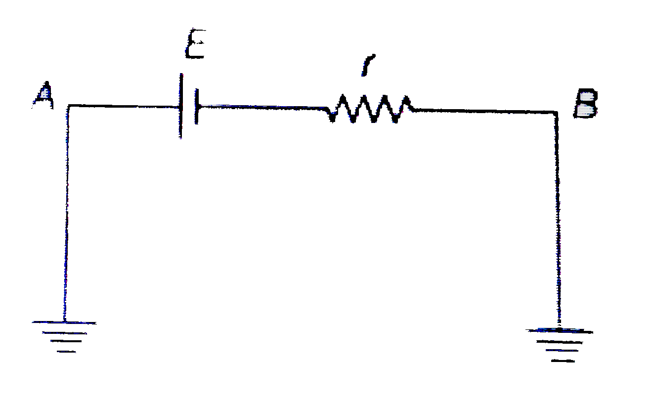
View SolutionBoth terminals of a battery of emf E and internal resistance r are grounded as shown. Select the correct alternative(s).

View SolutionAn inductor of inductance L = 8 H and a resistor of resistance R = 2Ω are connected in series with a battery of emf E = 10 V as shown in the figure. If the switch is closed at t = 0, then the voltage drop across the inductor at t = 1 s will be in volts)
View SolutionAn uncharged capacitor of capacitance C is connected with a battery of EMF V and a resistance R. The switch is closed at t=0. The time instant at which the current in the circuit is V4R is t=
View Solution
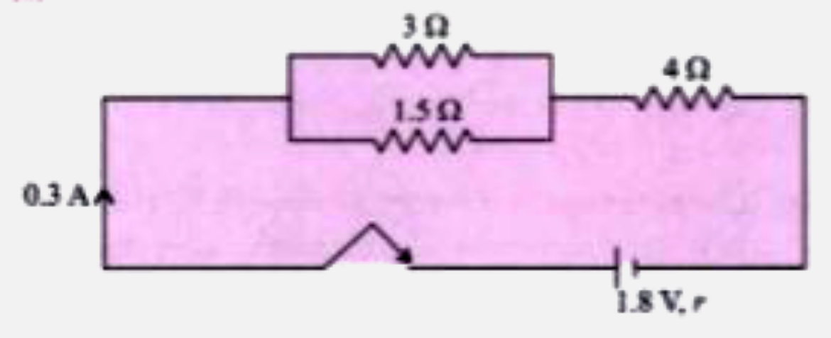
The diagram above shows three resistors connected across a cell of e.m.f. 1.8 V and internal resistance r. Calculate :
The internal resistance r.
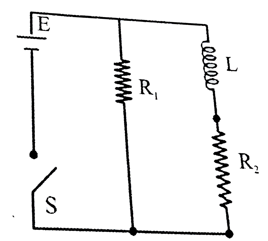
View SolutionAn inductor of inductance L = 400 mH and resistors of resistance R1=2Ω and R2=2Ω are connected to a battery of emf 12 V as shown in the figure. The internal resistance of the battery is negligible. The switch S is closed at t=0. The potential drop across L as a function of time is

View SolutionAn inductor of inductance L = 400 mH and resistors of resistance R1=2Ω and R2=2Ω are connected to a battery of emf 12 V as shown in the figure. The internal resistance of the battery is negligible. The switch S is closed at t=0. The potential drop across L as a function of time is

View SolutionAn inductor of inductance L = 400 mH and resistors of resistance R1=2Ω and R2=2Ω are connected to a battery of emf 12 V as shown in the figure. The internal resistance of the battery is negligible. The switch S is closed at t=0. The potential drop across L as a function of time is

View SolutionAn inductor coil of resistance 10Ω and inductance 120 mH is connected across a battery of emf 6 V and internal resistance 2Ω. Find the charge which flows through the inductor in (a) 10 ms, (b) 20ms and (c ) 100ms after the connections are made.
View Solution

