You have following material :
An ammeter ( 0-1A0 ,a voltmeter ( 0-3V) , a resistor of 20Ω , a key, a rheostat, a battery of 3 V and seven connecting wires.
Using this material draw a labelled circuit diagram to study the dependence of potential difference (V) across a resistor ont he current (I) passing through it.
To draw a labeled circuit diagram to study the dependence of potential difference (V) across a resistor on the current (I) passing through it, follow these steps:
1. Identify Components:
- You have the following components:
- Ammeter (0-1A)
- Voltmeter (0-3V)
- Resistor (20 Ω)
- Key (switch)
- Rheostat
- Battery (3V)
- Connecting wires
2. Connect the Battery:
- Start by placing the battery in the circuit. Connect the positive terminal of the battery to one terminal of the key (switch).
3. Add the Key:
- Connect the other terminal of the key to one end of the rheostat. This allows you to adjust the current in the circuit.
4. Connect the Rheostat:
- Connect the other terminal of the rheostat to one terminal of the ammeter. The ammeter measures the current flowing through the circuit.
5. Connect the Resistor:
- Connect the other terminal of the ammeter to one terminal of the resistor (20 Ω). The resistor is where you will measure the potential difference.
6. Connect the Voltmeter:
- Connect the voltmeter in parallel with the resistor. This allows you to measure the voltage across the resistor. Ensure that the positive terminal of the voltmeter is connected to the same side of the resistor as the ammeter.
7. Complete the Circuit:
- Connect the other terminal of the resistor back to the negative terminal of the battery to complete the circuit.
8. Label the Components:
- Clearly label each component in the diagram: Battery, Key, Rheostat, Ammeter, Resistor, and Voltmeter.
Circuit Diagram:
+−−−−−−(Key)−−−−−−(Rheostat)−−−−−−(Ammeter)−−−−−−(Resis→r)−−−−−−−∣|||⊢−−−−−−−−−−−−−−−−−(Vo<meter)−−−−−−−−−−−−−−−−−−−−−−−−|||±−−−−−−−−−−−−−−−−−−−−−−−−−−−−−−−−−−−−−−−−−−−−−−−−−−−−−−−+
- You have the following components:
- Ammeter (0-1A)
- Voltmeter (0-3V)
- Resistor (20 Ω)
- Key (switch)
- Rheostat
- Battery (3V)
- Connecting wires
- Start by placing the battery in the circuit. Connect the positive terminal of the battery to one terminal of the key (switch).
- Connect the other terminal of the key to one end of the rheostat. This allows you to adjust the current in the circuit.
- Connect the other terminal of the rheostat to one terminal of the ammeter. The ammeter measures the current flowing through the circuit.
- Connect the other terminal of the ammeter to one terminal of the resistor (20 Ω). The resistor is where you will measure the potential difference.
- Connect the voltmeter in parallel with the resistor. This allows you to measure the voltage across the resistor. Ensure that the positive terminal of the voltmeter is connected to the same side of the resistor as the ammeter.
- Connect the other terminal of the resistor back to the negative terminal of the battery to complete the circuit.
- Clearly label each component in the diagram: Battery, Key, Rheostat, Ammeter, Resistor, and Voltmeter.
+−−−−−−(Key)−−−−−−(Rheostat)−−−−−−(Ammeter)−−−−−−(Resis→r)−−−−−−−∣|||⊢−−−−−−−−−−−−−−−−−(Vo<meter)−−−−−−−−−−−−−−−−−−−−−−−−|||±−−−−−−−−−−−−−−−−−−−−−−−−−−−−−−−−−−−−−−−−−−−−−−−−−−−−−−−+
Similar Questions
Draw a labelled circuit diagram to study the dependence of current (I) on the potential
difference (V) across a resistor.
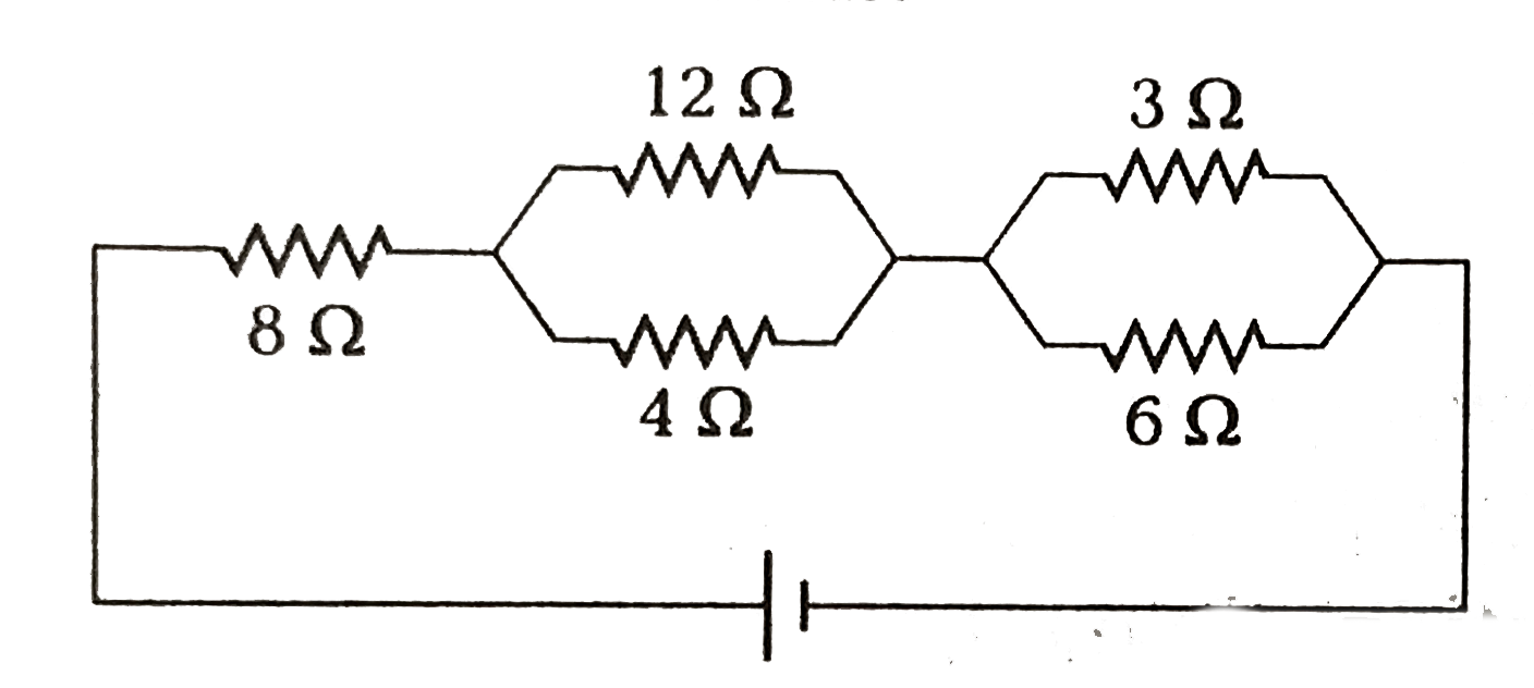
View SolutionIn the circuit diagram shown in figure, potential difference across 3Ω resistance is 20 V. Then, match the following two columns.

View SolutionTwo resistors of 4Ω and 6Ω are connected in parallel to a cell to draw 0.5 A current from the cell.
Draw a labelled circuit diagram showing the above arrangement.
View SolutionA circuit containing five resistors is connected to a battery with a 12 v emf as shown in figure. The potential difference across 4Ω resistor is

View SolutionResistors of 1, 2, 3 ohm are connected in the form of a triangle. If a 1.5V cell of negligible internal resistance is connected across 3 ohm resistor, the current flowing through this resistance will be
View SolutionA resistor of 6 Ω is connected in series with another resistor of 4 Ω. A potential difference of 20 V is applied across the combination. Calculate :
the current in the circuit,
View SolutionTwo resistors of 2.0 92 and 3.0 22 are connected
in parallel, with a battery of 60 V and negligible internal resistance. For each case draw a circuit diagram and calculate the current through the battery
View SolutionA car battery with a 12V e.m.f. and an internal resistance of 0.04Ω is being charged with a current of 50A.
The potential difference V across the terminals of the battery are:
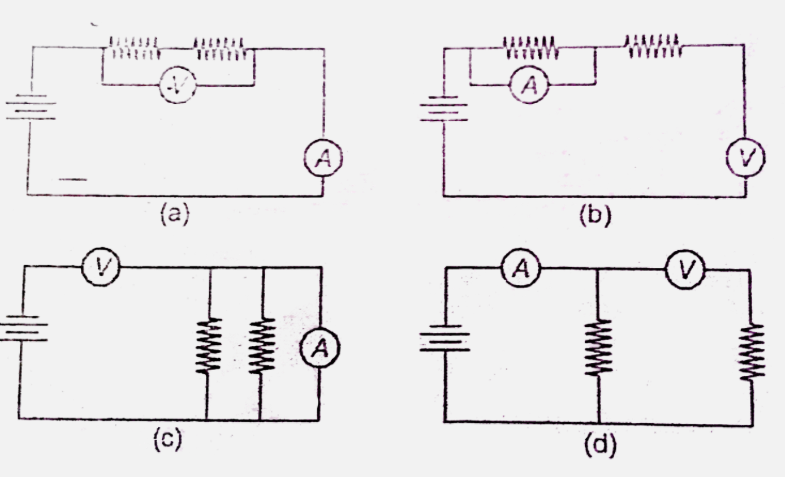
View SolutionVoltmeter V and Ammeter A are used to measure the total potential difference of the circuit and the current through each resistor. Which is the correct circuit ?

View SolutionA capacitor of capacity 2μF is changed to a potential different of 12V . It is then connected across an inductor of inductance 0.6mH What is the current in the circuit at a time when the potential difference across the capacitor is 6.0V ?
View Solution
