Draw a labelled circuit diagram to study the dependence of current (I) on the potential
difference (V) across a resistor.
To draw a labeled circuit diagram to study the dependence of current (I) on the potential difference (V) across a resistor (R), follow these steps:
1. Draw the Battery:
- Start by drawing a battery symbol. The longer line represents the positive terminal, and the shorter line represents the negative terminal.
Hint: Remember that the battery provides the necessary voltage for the circuit.
2. Add the Ammeter:
- Connect an ammeter in series with the battery. The ammeter is represented by a circle with an "A" inside it. This device measures the current flowing through the circuit.
Hint: The ammeter must be connected in series to measure the current accurately.
3. Draw the Resistor:
- Next, draw a resistor in series with the ammeter. The resistor is represented by a zigzag line or a rectangle.
Hint: The resistor is where the potential difference will be measured.
4. Connect the Voltmeter:
- Connect a voltmeter in parallel with the resistor. The voltmeter is represented by a circle with a "V" inside it. This device measures the voltage across the resistor.
Hint: The voltmeter should be connected in parallel to get the correct voltage reading across the resistor.
5. Add a Key (Switch):
- Include a key (switch) in the circuit. The key is represented by a break in the line with a small circle. When the key is closed, the circuit is complete.
Hint: The key allows you to open or close the circuit, controlling the flow of current.
6. Label the Components:
- Clearly label each component in the circuit diagram: Battery (V), Ammeter (A), Resistor (R), Voltmeter (V), and Key (K).
Hint: Proper labeling helps in understanding the function of each component in the circuit.
7. Indicate Current Flow:
- Draw arrows to indicate the direction of current flow from the positive terminal of the battery through the ammeter, resistor, and back to the negative terminal of the battery.
Hint: Current flows from the positive to the negative terminal in a closed circuit.
Final Circuit Diagram:
- The final circuit diagram should show the battery, ammeter, resistor, voltmeter, and key, all connected as described above, with appropriate labels.
Conclusion:
This circuit diagram allows you to study the relationship between current (I) and potential difference (V) across the resistor, demonstrating Ohm's Law (V = IR).
---
- Start by drawing a battery symbol. The longer line represents the positive terminal, and the shorter line represents the negative terminal.
- Connect an ammeter in series with the battery. The ammeter is represented by a circle with an "A" inside it. This device measures the current flowing through the circuit.
- Next, draw a resistor in series with the ammeter. The resistor is represented by a zigzag line or a rectangle.
- Connect a voltmeter in parallel with the resistor. The voltmeter is represented by a circle with a "V" inside it. This device measures the voltage across the resistor.
- Include a key (switch) in the circuit. The key is represented by a break in the line with a small circle. When the key is closed, the circuit is complete.
- Clearly label each component in the circuit diagram: Battery (V), Ammeter (A), Resistor (R), Voltmeter (V), and Key (K).
- Draw arrows to indicate the direction of current flow from the positive terminal of the battery through the ammeter, resistor, and back to the negative terminal of the battery.
- The final circuit diagram should show the battery, ammeter, resistor, voltmeter, and key, all connected as described above, with appropriate labels.
This circuit diagram allows you to study the relationship between current (I) and potential difference (V) across the resistor, demonstrating Ohm's Law (V = IR).
Similar Questions
You have following material :
An ammeter ( 0-1A0 ,a voltmeter ( 0-3V) , a resistor of 20Ω , a key, a rheostat, a battery of 3 V and seven connecting wires.
Using this material draw a labelled circuit diagram to study the dependence of potential difference (V) across a resistor ont he current (I) passing through it.
View SolutionWhich of the following is the correct set-up for studying the dependence of the current on the potential difference across a resistor and why?

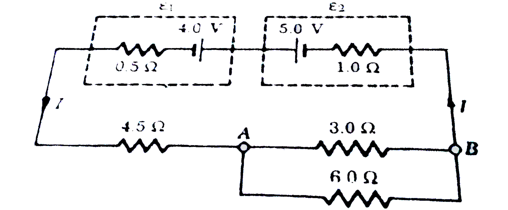
View SolutionIn the circuit shown in figure potential difference across
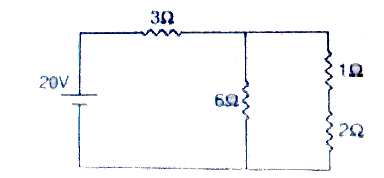
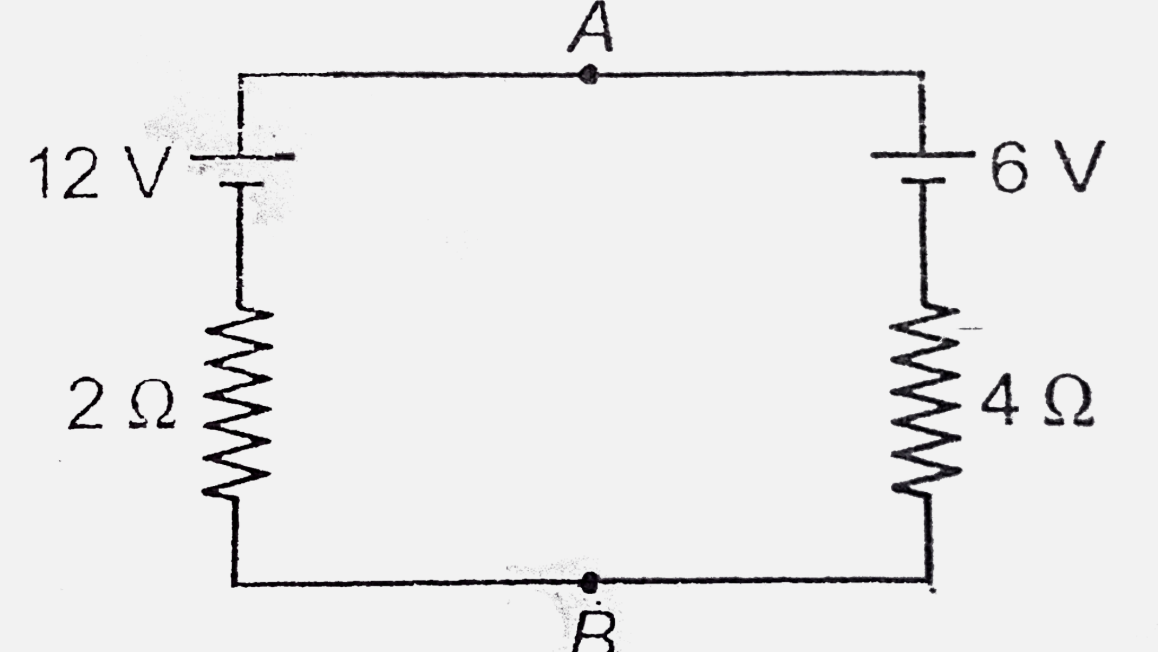
View SolutionIn the shown circuit, what is the potential difference across A and B
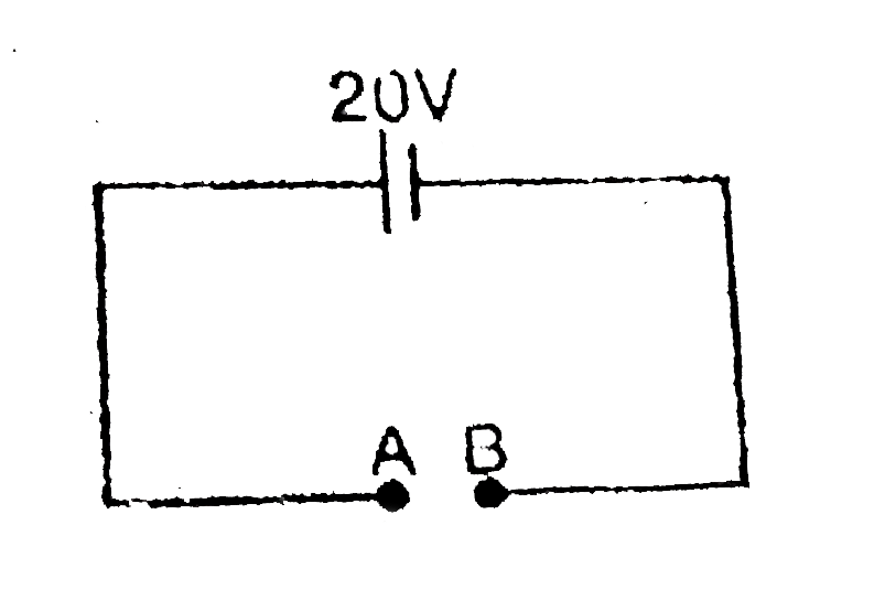
View SolutionIn the given circuit, with steady current, the potential difference across the capacitor is
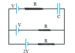
View SolutionDraw a well labelled circuit diagram for the verification of Ohm.s law.
View SolutionIn the given circuit diagram find the potential difference across 2Ω resistance (in volts).
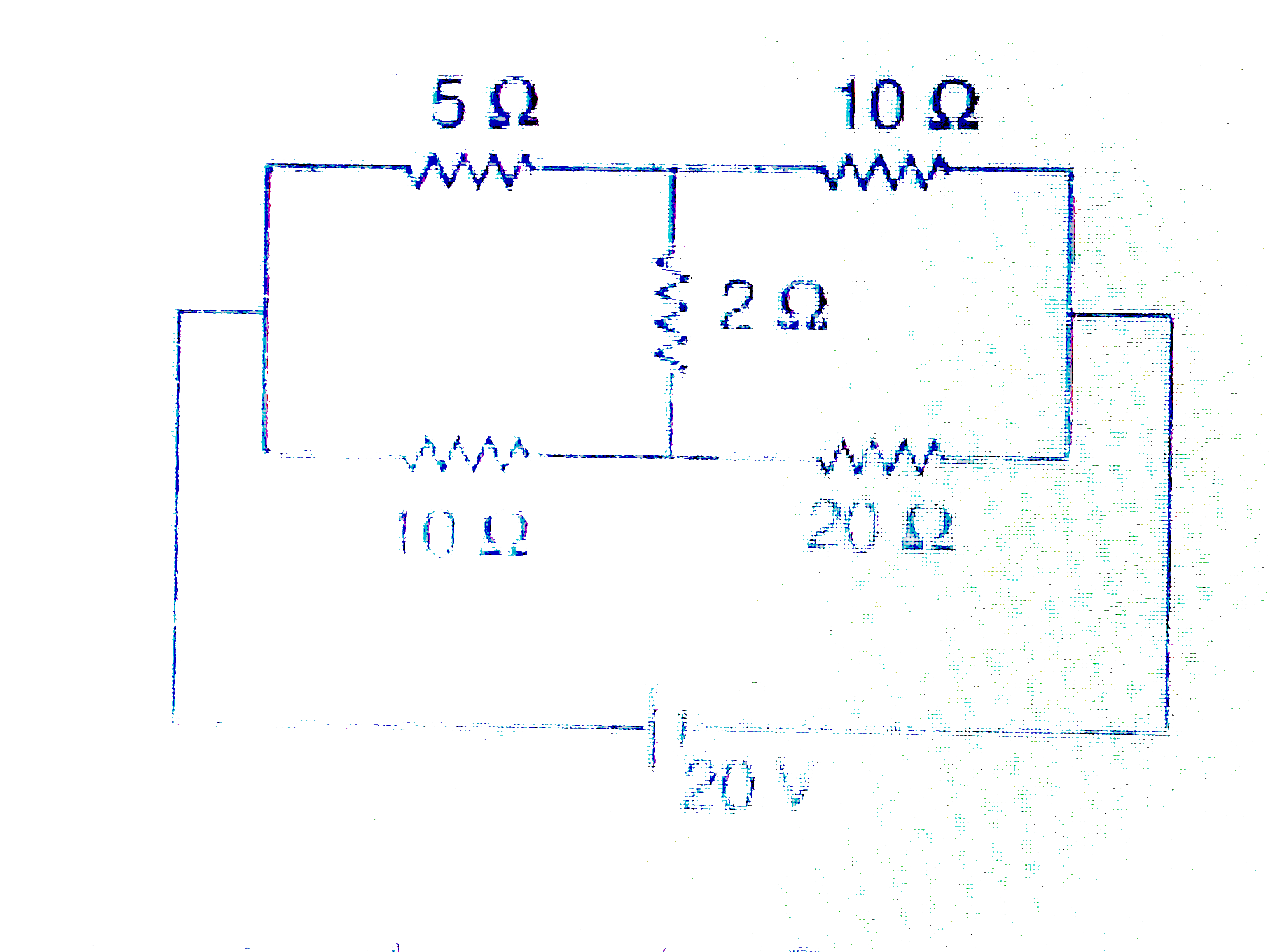
View SolutionIn the circuit shown in Fig. 4.41, calculate the current in each resistor and potential difference across each resistor.
View SolutionPotential difference across AB , i.e., VA−VB is
View SolutionDraw the labelled diagram of V.S. of maize seed.
View Solution