How will you conclude that the same potential difference (voltage) exists across three resistors connected in a parallel arrangement to a battery ?
To conclude that the same potential difference (voltage) exists across three resistors connected in a parallel arrangement to a battery, we can follow these steps:
Step 1: Understand the Circuit Configuration
In a parallel circuit, all components are connected across the same two points. In this case, we have three resistors (R1, R2, and R3) connected in parallel to a battery.
Step 2: Identify the Battery Voltage
Let’s denote the voltage of the battery as V. The positive terminal of the battery is at a higher potential (V volts), and the negative terminal is at a lower potential (0 volts).
Step 3: Label the Points in the Circuit
We can label the points in the circuit for clarity:
- Let point A be connected to the positive terminal of the battery (V volts).
- Let points B and C also be connected to the positive terminal (V volts).
- Let points D, E, and F be connected to the negative terminal of the battery (0 volts).
Step 4: Determine the Potential at Each Point
From the arrangement:
- The potential at points A, B, and C (connected to the positive terminal) is V volts.
- The potential at points D, E, and F (connected to the negative terminal) is 0 volts.
Step 5: Calculate the Potential Across Each Resistor
Now, we can calculate the potential across each resistor:
- For resistor R1, the potential difference (V1) is given by:
V1=VA−VD=V−0=V
- For resistor R2, the potential difference (V2) is given by:
V2=VB−VE=V−0=V
- For resistor R3, the potential difference (V3) is given by:
V3=VC−VF=V−0=V
Step 6: Conclude the Result
Since the potential across each resistor (R1, R2, and R3) is the same (V volts), we conclude that:
V1=V2=V3=V
Thus, the same potential difference exists across all three resistors connected in parallel.
Summary
In conclusion, the voltage across resistors R1, R2, and R3 is equal, confirming that the same potential difference exists across them when connected in parallel to a battery.
---
In a parallel circuit, all components are connected across the same two points. In this case, we have three resistors (R1, R2, and R3) connected in parallel to a battery.
Let’s denote the voltage of the battery as V. The positive terminal of the battery is at a higher potential (V volts), and the negative terminal is at a lower potential (0 volts).
We can label the points in the circuit for clarity:
- Let point A be connected to the positive terminal of the battery (V volts).
- Let points B and C also be connected to the positive terminal (V volts).
- Let points D, E, and F be connected to the negative terminal of the battery (0 volts).
From the arrangement:
- The potential at points A, B, and C (connected to the positive terminal) is V volts.
- The potential at points D, E, and F (connected to the negative terminal) is 0 volts.
Now, we can calculate the potential across each resistor:
- For resistor R1, the potential difference (V1) is given by:
V1=VA−VD=V−0=V
- For resistor R2, the potential difference (V2) is given by:
V2=VB−VE=V−0=V
- For resistor R3, the potential difference (V3) is given by:
V3=VC−VF=V−0=V
Since the potential across each resistor (R1, R2, and R3) is the same (V volts), we conclude that:
V1=V2=V3=V
Thus, the same potential difference exists across all three resistors connected in parallel.
In conclusion, the voltage across resistors R1, R2, and R3 is equal, confirming that the same potential difference exists across them when connected in parallel to a battery.
Topper's Solved these Questions
Similar Questions
Knowledge Check
A voltmeter having a resistance of 1800Ω employed to measure the potential difference across a 200Ω resistor which is connected to the terminals of a dc power supply having an emf of 50 V and an internal resistance of 20Ω. What is the percentage decrease in the potential difference across the 200Ω resistor as a result of connecting the voltmeter across it?
A1%B5%C10%D25%
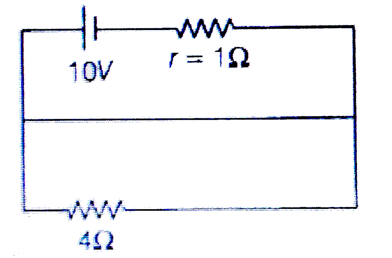
Potential different across the terminals of the battery shown in figure is

View SolutionDraw a circuit diagram of an electric circuit containing a cell, a key, an ammeter, a resistance of 2Ω in series with a combination of two resistors (4Ω each) in parallel and a voltmeter across the parallel combination. Will the potential difference across the 2Ω resistor be the same as that across the parallel combination of 4Ω resistors ? Give reason.
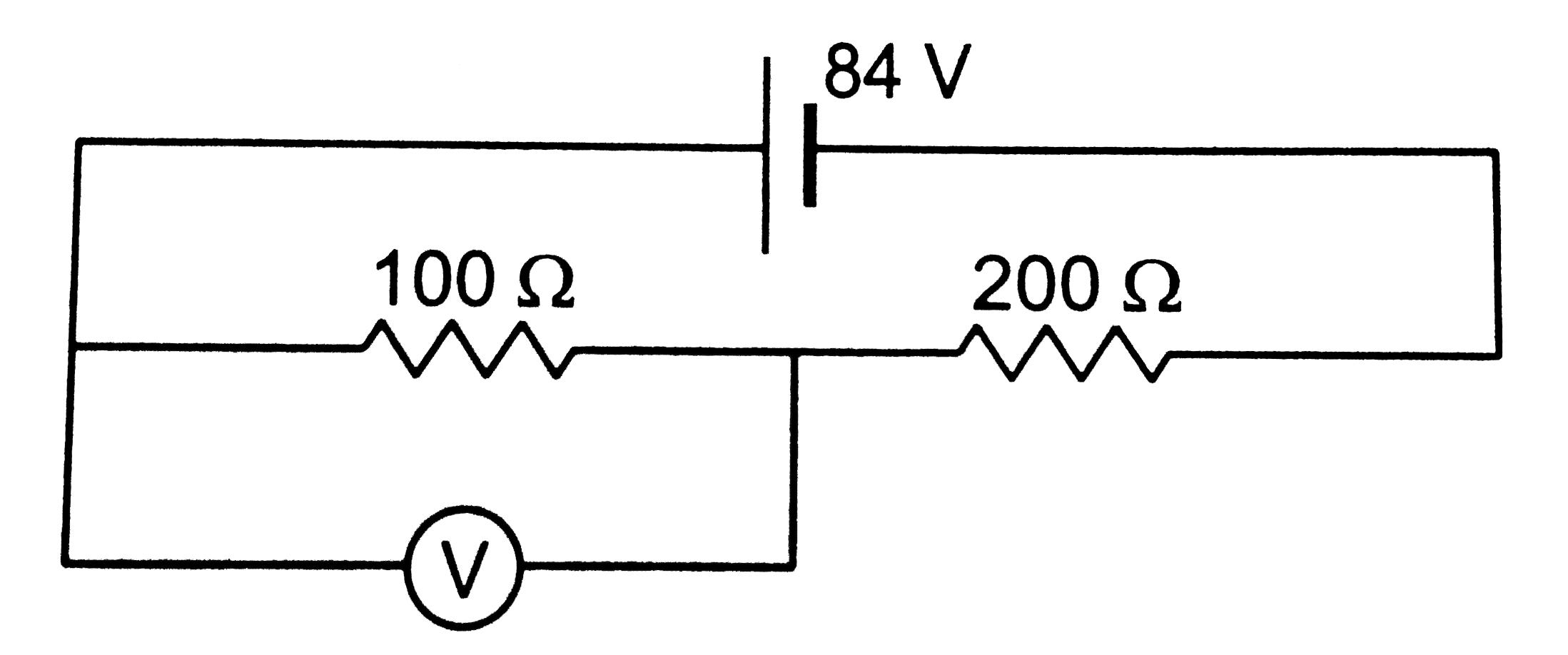
View SolutionA voltmeter of resistances 400(Ω)is used to measure the potential difference across the 100(Ω)resistor in the circuit shown in figure.(a) What will be the reading of the voltmeter ?(b) What was the potential difference across 100(Ω)before the voltmeter was connected ?

View SolutionHow will you infer with the help of an experiment that the same current flows through every part of the circuit containing three resistances in series connected to a battery ?
View SolutionFour equal resistance dissipated 5 W of power together when connected in series to a battery of negligible internal resistance . The total power dissipated in these resistance when connected in parallel across the same battery would be .
View SolutionA capacitance C, a resistance R and an emf (ε)are connected in series at t=0.What is the maximum value of (a) the potential difference across the resistor, (b) the current in the circuit,(c )the potential difference across the capacitor, (d) the energy stored in the capacitor ,(e)the power delivered by the battery and (f) the power converted int heat.
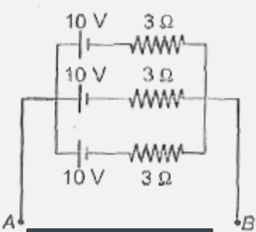
View SolutionThree identical cells are connected in parallel across AB. Net across AB is

View Solution
