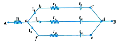
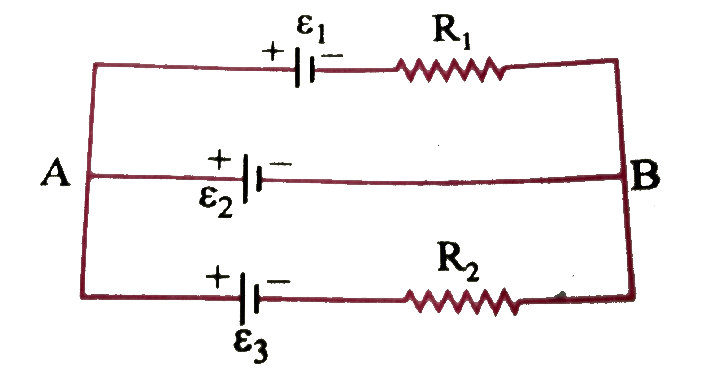
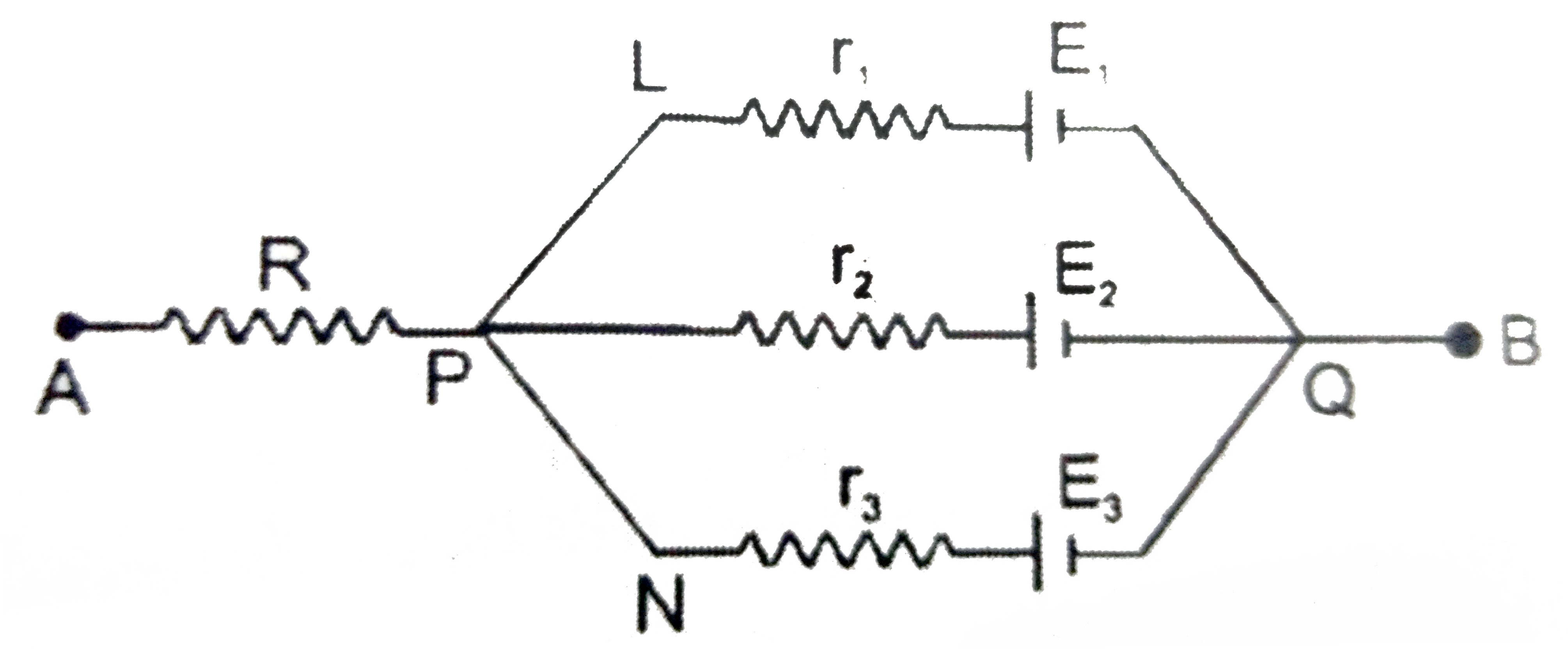
In the circuit shown in figure, ε1= 3 V, ε2=2V,ε3=IV and R=r1=r2=r3=1Ω .
The current through each branch is...... and potential difference between the points A and B is .......
 Solution in Gujrati
Let I1,I2andI3 be the currents through the resistors r1,r2andr3 respectively as indicated in figure. Using Kirchoff.s second rule to loops abaca and abcdefa we have,
I1r1−ε1+ε2+I2r2=0 ..... (1)
I1r1−ε1+ε3+I3r3=0 ..... (2)
From equation (1) and (2),
ε1−I1r1=ε2+I2r2=ε3+I3r3 .... (3)
Applying Kirchoff.s first rule to junction a, we have I1=I1+I3 .... (4)
Using equation (4) in (3) , we get ,
ε1−(I2+I3)r1=ε3+I3r3
or, 2I3+I2=2 .... (5)
Also ε2+I2r2=ε3+I3r3
or , I3−I2=I .... (6)
From equation (4) , (5) and (6) ,
I1=IA,I2=0AandI3=1A
Potential difference between A and B
= Potential difference between a and d
= ε1−I1r1=3−1×1=2 V
Topper's Solved these Questions
- CURRENT ELECTRICITYBOOK - KUMAR PRAKASHANCHAPTER - CURRENT ELECTRICITYEXERCISE - SECTION [B] (NUMERICAL)
10 Videos
- CURRENT ELECTRICITYBOOK - KUMAR PRAKASHANCHAPTER - CURRENT ELECTRICITYEXERCISE - SECTION C NCERT EXEMPLAR SOLUTION (MULTIPLE CHOICE QUESTIONS (MCQs))
6 Videos
- CURRENT ELECTRICITYBOOK - KUMAR PRAKASHANCHAPTER - CURRENT ELECTRICITYEXERCISE - SECTION [B] (NUMERICAL FROM TEXTUAL EXERCISE)
35 Videos
- BOARD'S QUESTION PAPER MARCH-2020 BOOK - KUMAR PRAKASHANCHAPTER - BOARD'S QUESTION PAPER MARCH-2020 EXERCISE - PART-B SECTION -C
4 Videos
- DUAL NATURE OF RADIATION AND MATTERBOOK - KUMAR PRAKASHANCHAPTER - DUAL NATURE OF RADIATION AND MATTEREXERCISE - Section-D (MCQs asked in GUJCET/Board Exam)
1 Video
Similar Questions
One copper wire having resistivity 1.7 ×10⁻⁸Ω, density 8.9×10³kgm−3, atomic weight 63.5 g mol−1 , length 0.1 m and cross-sectional area 10−6m2carries 1 A electric current. Find (i) potential difference across the wire (ii) drift velocity of free electron. (Avogadro number = 6.02×10²³ mol−1 and valency of copper - 1
View SolutionConsider a current carrying wire (current I) in the shape of a circle. Note that as the current progresses along the wire, the direction of J (current density) changes in an exact manner, while the current I remain unaffected. The agent that is essentially responsible for is
View SolutionThe storage battery of a car has an emf of 12 V. If the internal resistance of the battery is 0.4 Ω , what is the maximum current that can be drawn from the battery ?
View SolutionDerive an expression for current I passing through an AC circuit containing only inductor L. Draw a Phasor diagram and graph of v and I versus ωt. Explain instantaneous power and the average power.
View SolutionMass of photon in motion is ………
View SolutionThree dielectrics of relative permittivities epsilon_(r_(1))=1,epsilon_(r_(2))=2 , and epsilon_(r_(3))=3 are introduced in a parallel plate capacitor of plate A and B. .
View SolutionA parallel combination of two cells of emfs ε1 and ε2, and internal resistance r1 and r2 is used to supply current to a load of resistance R. Write the expression for the current through the load in terms of ε1,ε2,r1 and r2.
View SolutionFind the current flowing through the resistance R1 of the circuit shown in Fig. If the resistances are equal to R1=10Ω.R2=20Ω and R3=30Ω, and the potential of points 1,2 and 3 are equal to φ1=10V,φ2=6V, and φ3=5V
View SolutionIn Fig. 4.32 epsilon_(1) " and " epsilon_(2) are respectively 2.0 V and 4.0 V the resistances r_(1),r_(2) and R are respectively 1.0 Omega, 2.0 Omega " and " 5.0 Omega . Calculate the current in the circuit. Also calculate (i) potential difference between the points b and a, (ii) potential difference between a and c.
View SolutionIn the circuit as shown in figure, E_(1)=2V , E_(2)=2V, E_(3)=1V, and R=r_(1)=r_(2)=r_(3)Omega . The potential difference between points A and B will be
View Solutionदो बैटरी जिनका वि वा बल ε1 व ε2एवं इनके आंतरिक क्रमशः r1 व r2 को निम्न चित्रानुसार समांतर क्रम में संयोजित किया गया है ।ε1 व ε2 के मध्य समतुल्य वि वा बल ε
View Solutionनीचे दिए गये चित्र में ε1=ε2=ε3=2 वाल्ट तथा R1=R2=4 ओम । A और B के बीच सेल ε2 से बहने वाली धारा है -
View SolutionIn the circuit shown in fig. E1=3 volt,E2=2 volt,E3=1 vole and R=r1=r2=r3=1ohm.
(i) Find potential difference in Volt between the points A and B with A & B unconnected.
(ii) If r2 is short circuited and the point A is coneted to point B through a zero resistance wire, find the current through R in ampere.
View SolutionIn the circuit shown, E_(1)= 7 V, E_(2) = 7 V, R_(1) = R_(2) = 1Omega and R_(3) = 3 Omega respectively. The current through the resistance R_(3)
View SolutionTwo batteries of emf ε1andε2(ε2>ε1) and internal resistances r1andr2 respectively are connected in parallel as shown in figure.
View Solution