Capacitance C is 15.0 μF and the sinusoidal alternating emf device operates at amplitude Em = 36.0 V and frequency fd= 60.0 Hz.
(a) What are the potential difference VC(t) across the capacitance and the amplitude VC of Vc(t) ?
(b) What are the current IC(t) in the circuit as a function of time and the amplitude IC of Ic(t) ?
In a circuit with a purely capacitive load, the potential difference vC(t) across the resistance is always equal to the potential difference E(t) across the emf device.
Calculations : Here we have vC(t)=E(t) and Vc=Em. Since Em is given, we have
VC=Em=36.0 V.
To find vC(t),
vC(t)=E(t)=Emsinωdt .
Then, substituting Em = 36.0 V and ωd=2πfd=120π , we have
vC=(36.0V)sin(120πt)
(b) What are the current iC(t) in the circuit as a function of time and the amplitude IC of iC(t) ? In an ac circuit with a purely capacitive load, the alternating current iC(t) in the capacitance leads the alternating potential difference vC(t) by 90∘ , that is , the phase constant ϕ for the current is −90∘ , or −π/2 rad.
Calculation: Thus, we can write
iC=ICsin(ωdt−ϕ)=ICsin(ωdt+π/2)
We can find the amplitude IC (VC=ICXC) if we first find the capacitance reactance XC. (XC=1/ωdC), with ωd=2πfd, we can write
XC=12πfdC=1(2π)(60.0Hz)(15.0×10⁻⁶F)
=177Ω.
The current amplitude is
IC=VCXC=36.0V177Ω=0.203 A
Substituting this and ωd=2πfd=120π , we have
iC=(0.203A)sin(120πt+π/2)
Topper's Solved these Questions
- ELECTROMAGNETIC OSCILLATIONS AND ALTERNATING CURRENT BOOK - RESNICK AND HALLIDAYCHAPTER - ELECTROMAGNETIC OSCILLATIONS AND ALTERNATING CURRENT EXERCISE - Check Point
8 Videos
- ELECTROMAGNETIC OSCILLATIONS AND ALTERNATING CURRENT BOOK - RESNICK AND HALLIDAYCHAPTER - ELECTROMAGNETIC OSCILLATIONS AND ALTERNATING CURRENT EXERCISE - Problems
30 Videos
- ELECTROMAGNETIC INDUCTIONBOOK - RESNICK AND HALLIDAYCHAPTER - ELECTROMAGNETIC INDUCTIONEXERCISE - PRACTICE QUESTIONS (Integer Type)
14 Videos
- ELECTROMAGNETIC WAVES BOOK - RESNICK AND HALLIDAYCHAPTER - ELECTROMAGNETIC WAVES EXERCISE - PRACTICE QUESTIONS (Integer Type)
3 Videos
Similar Questions
Inductance L is 230 mH and the sinusoidal alternating emf device operates at amplitude Em =36.0 V and frequency fd=60.0 Hz.
(a) What are the potential difference vL(t) across the inductance and the amplitude VL of vL(t) ?
View SolutionResistance R is 200 Ω and the sinusoidal alternating emf device operates at amplitude Em=36.0 V and frequency fd=60.0 Hz.
(a) What is the potential difference vR(t) across the resistance as a function of time t, and what is the amplitude VR of VR(t) ? (b)What is the current vR(t) in the resistance and the amplitude IR of IR(t) ?
View Solution
Knowledge Check
The potential differences across the resistance, capacitance and inductance are 80V, 40V and 100V respectively in an L-C-R circuit. The power factor of this circuit is
A1.0B0.4C0.5D0.8The potential differences across the resistance, capacitance and inductance are 80V,40V and 100V respectively in an L−C−R circuit. The power factor of this circuit is
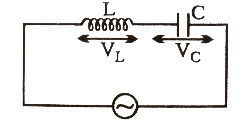
A0.8B1.0C0.4D0.5The current I, potential difference VL across the inductor and potential difference VC across the capacitor in circuit as shown in the figure are best represented vectorially as
 A
A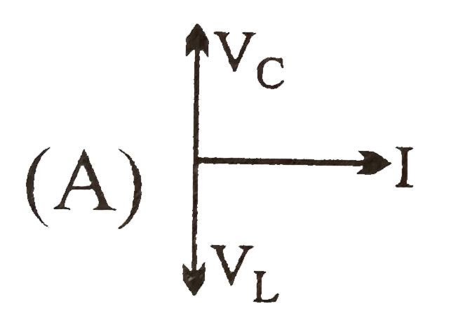 B
B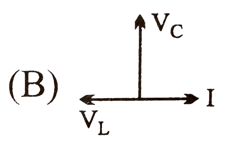 C
C D
D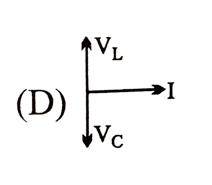
An inductor of inductance 1 H is connected across an A C supply . The current in the circuit is a sinusoidal function of time with amplitude 0.5 A and frequency 50 Hz. Calculate the effective potential difference across the inductor .
View SolutionFind the dimension of CV where C= Capacitance and V is potential difference
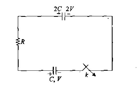
View SolutionTwo parallel plate capacitor of capacitance 2C and C are charged to the potentials 2 V and V respectively and are connected in a circuit along with a resistance R as shown in the diagram. The switch k is closed at t=0. Find the current in the circuit as a function of time and total heat produced in the circuit
View SolutionA circuit consisting of a capacitor with capacitance C and a resistance R connected in series was connected at the moment t=0 to a source of ac voltage V=Vmcosωt . Find the current in the circuit as a function of time t.
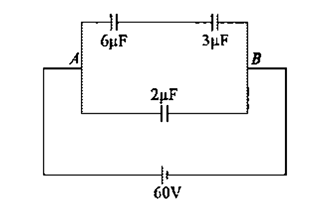
View SolutionIn the circuit shown, the potential difference across the 3μF capacitor is V and the equivalent capacitance between A and B is C Then:
View Solution
