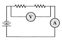
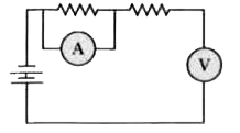
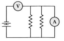
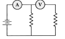
Which circuit diagram shows voltmeter V and ammeter A correctly positioned to measure the total potential difference of the circuit and the current through each resistor?
The correct Answer is:A
To solve the question regarding the correct positioning of a voltmeter and ammeter in a circuit diagram, we can follow these steps:
1. Understand the Function of the Instruments:
- A voltmeter measures the potential difference (voltage) across two points in a circuit and must be connected in parallel with the component across which the voltage is to be measured.
- An ammeter measures the current flowing through a circuit and must be connected in series with the circuit elements.
2. Analyze the Options:
- We have four options to consider. We need to determine which option correctly places the voltmeter in parallel and the ammeter in series.
3. Evaluate Each Option:
- Option 1: The voltmeter is connected in parallel and the ammeter is connected in series.
- This option is correct because it follows the rules for connecting these instruments.
- Option 2: The voltmeter is connected in series and the ammeter is connected in parallel.
- This option is incorrect because the voltmeter should not be in series.
- Option 3: Both the voltmeter and ammeter are connected in series.
- This option is incorrect because the voltmeter must be in parallel.
- Option 4: Similar to option 3, both are connected in series.
- This option is also incorrect for the same reason.
4. Conclusion:
- After evaluating all options, we find that Option 1 is the only correct configuration where the voltmeter is in parallel and the ammeter is in series.
Final Answer:
The correct circuit diagram is Option 1.
- A voltmeter measures the potential difference (voltage) across two points in a circuit and must be connected in parallel with the component across which the voltage is to be measured.
- An ammeter measures the current flowing through a circuit and must be connected in series with the circuit elements.
- We have four options to consider. We need to determine which option correctly places the voltmeter in parallel and the ammeter in series.
- Option 1: The voltmeter is connected in parallel and the ammeter is connected in series.
- This option is correct because it follows the rules for connecting these instruments.
- Option 2: The voltmeter is connected in series and the ammeter is connected in parallel.
- This option is incorrect because the voltmeter should not be in series.
- Option 3: Both the voltmeter and ammeter are connected in series.
- This option is incorrect because the voltmeter must be in parallel.
- Option 4: Similar to option 3, both are connected in series.
- This option is also incorrect for the same reason.
- After evaluating all options, we find that Option 1 is the only correct configuration where the voltmeter is in parallel and the ammeter is in series.
The correct circuit diagram is Option 1.
Topper's Solved these Questions
- CIRCUITSBook:RESNICK AND HALLIDAYChapter:CIRCUITSExercise:Practice Questions (More than One Correct Choice Type)
Explore 12 Videos
- CIRCUITSBook:RESNICK AND HALLIDAYChapter:CIRCUITSExercise:Practice Questions (Linked Comprehension)
Explore 11 Videos
- CIRCUITSBook:RESNICK AND HALLIDAYChapter:CIRCUITSExercise:Problems
Explore 45 Videos
- CENTER OF MASS Book:RESNICK AND HALLIDAYChapter:CENTER OF MASS Exercise:Practice Questions (Integer )
Explore 4 Videos
- CIRCULAR MOTIONBook:RESNICK AND HALLIDAYChapter:CIRCULAR MOTIONExercise:CHECK POINTS
Explore 6 Videos
Similar Questions
Knowledge Check
It is required to measure equivalent ressitance of circuit with ideal battery, ideal voltmeter and ideal ammeter. Which circuit diagram shows voltmeter V and ammter. A correctly position to measure the total resistance of circuit ?
A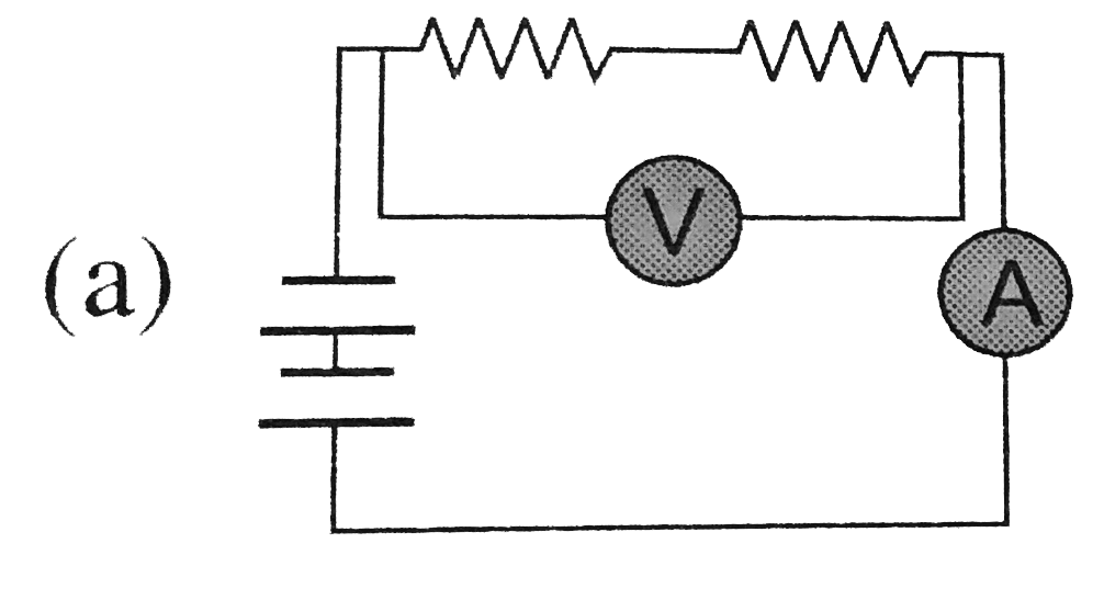 B
B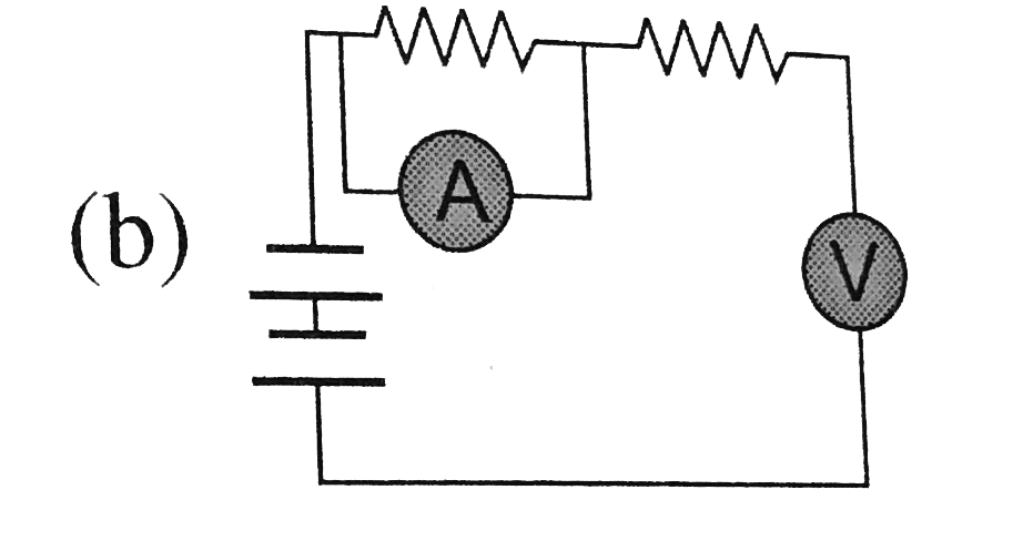 C
C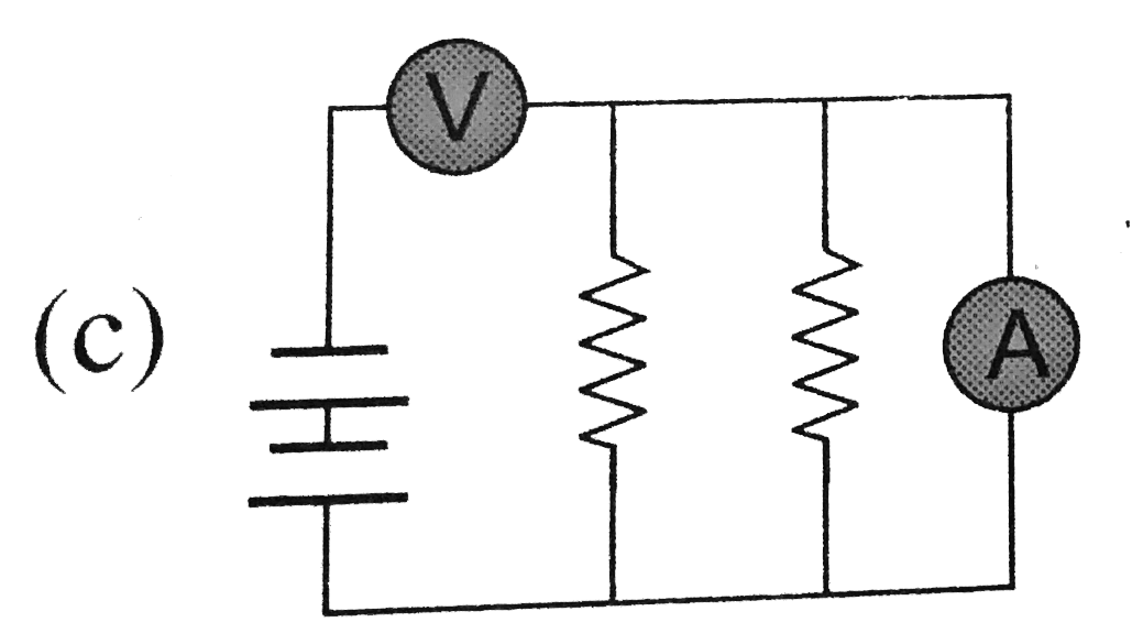 D
D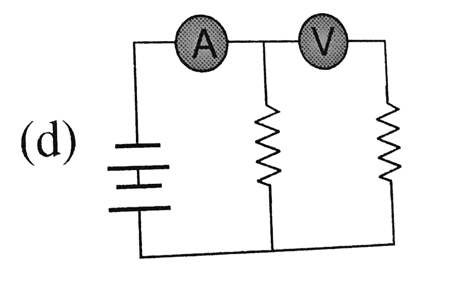
Which circuit will not show current in ammeter ?
A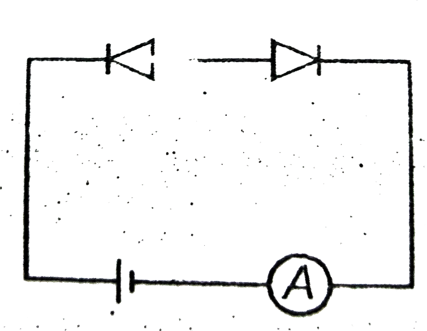 B
B C
C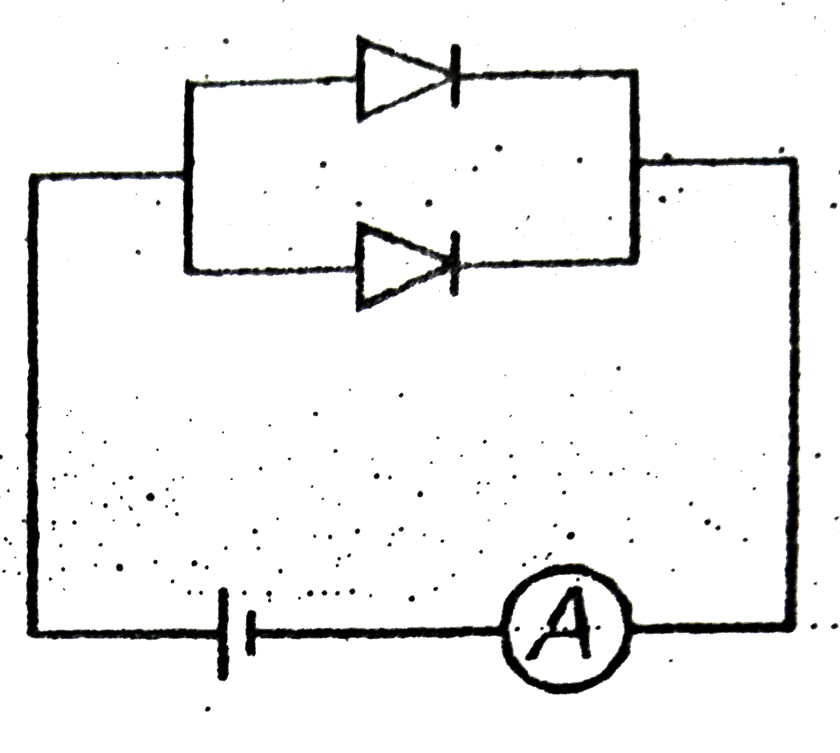 D
D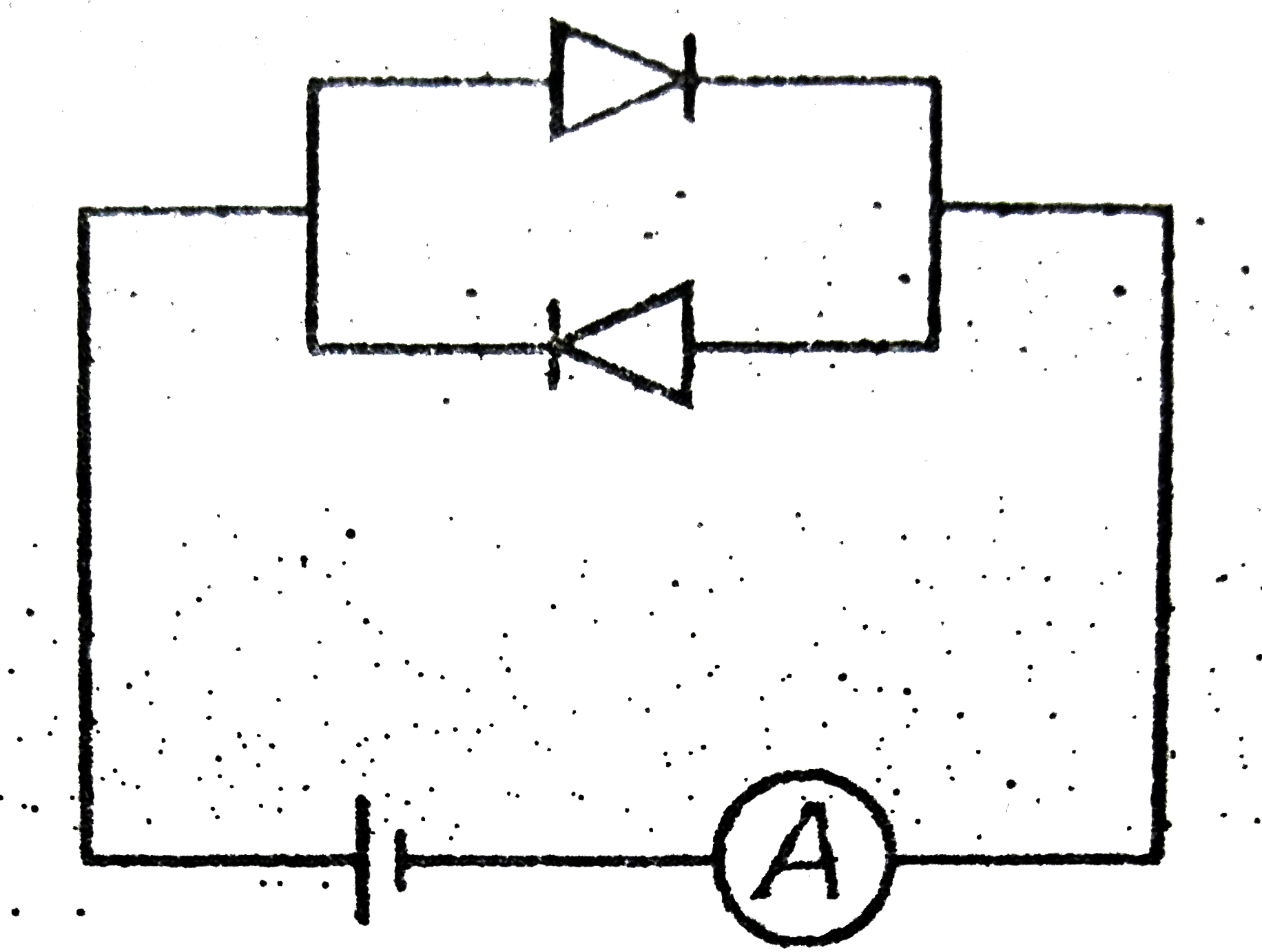
Which circuit will not show current in ammeter ?
A B
B C
C D
D
How is a voltmeter connected in a circuit to measure the potential difference between two points ?
View SolutionIn the circuit diagram shown in find the current through the 1Ω resistor.

View SolutionThe following circuit diagram shows the experimental set-up for the study of dependence of current on potential difference. Which two circuit components are connected in series?
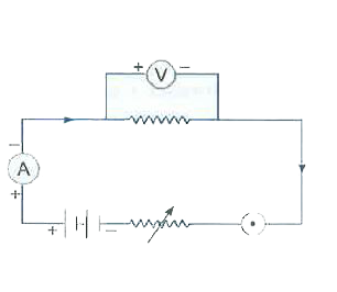
View SolutionWhich circuit will not show current in ammeter ?
View SolutionHow is voltmeter connected in the circuit to measure potential difference between two points ?
View Solution

