Figure 25-41 shows a circuit section of four air filled capacitors that is connected to a larger circuit. The graph below the section shows the electrin potential V(x) as a function of position x along the lower part of the section, through capacitor 4. Similarly the graph above the section shows the electric potential V(x) as a function of position x along the upper part of the section, through capacitors 1,2 and 3 capacitors 3 has a capacitance of 1.60μF What are the capacitances of (a) capacitor 1 and (b) capacitor 2?
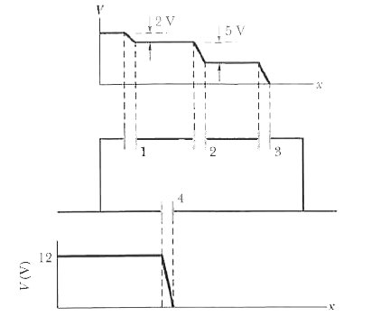
a)4.0μFb)1.6μF
Topper's Solved these Questions
- CAPACITANCEBOOK - RESNICK AND HALLIDAYCHAPTER - CAPACITANCEEXERCISE - PRACTICE QUESTIONS (SINGLE CORRECT CHOICE TYPE)
23 Videos
- CAPACITANCEBOOK - RESNICK AND HALLIDAYCHAPTER - CAPACITANCEEXERCISE - PRACTICE QUESTIONS (MORE THAN ONE CORRECT CHOICE TYPE)
12 Videos
- CAPACITANCEBOOK - RESNICK AND HALLIDAYCHAPTER - CAPACITANCEEXERCISE - CHECKPOINTS
4 Videos
- ALL ABOUT ATOMS BOOK - RESNICK AND HALLIDAYCHAPTER - ALL ABOUT ATOMS EXERCISE - CHECKPOINT
1 Videos
- CENTER OF MASS BOOK - RESNICK AND HALLIDAYCHAPTER - CENTER OF MASS EXERCISE - Practice Questions (Integer )
4 Videos
Similar Questions
Knowledge Check
Shows a part of a circuit. If all the capacitors have a capacitance of 2μF, then the
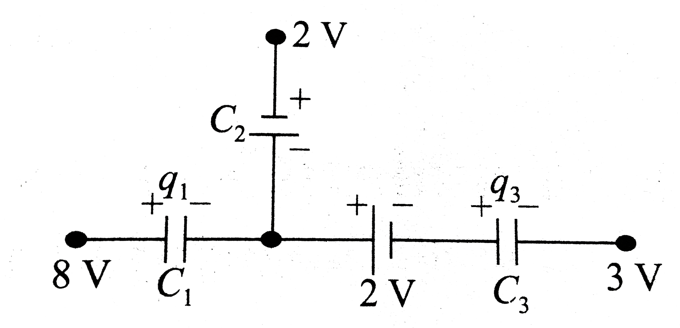 . Acharge on C3 is zeroBcharge on C3 is 12μCCcharge on C1 is 6μCDcharge on C1 in 6μC
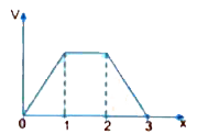
A capacitor is connected to a variable source of potential. Current flowing in the circuit and potential across the plates of capacitor at time t are shown in figure.

Capacity of the capacitor isA1 FB2 FC3 FD4 FFigure show two capacitors connected in series and joind to a bettery. The graph shows the variation in potential as one movies from left to right on the branch containing the capacitors.
 AC1>CBC1=C2CC1<C2DThe information is not sufficient to decide the ralation between Q+ and Q.
Figure shows the connection of two ideal diodes and two capacitors C and 2C. A 120-volt battery is connected to the input terminals with a at positive potential and b at lower potential. Find the putput voltage.

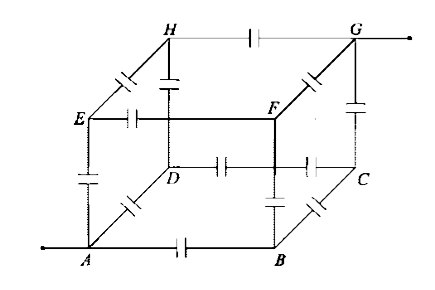
View SolutionFigure shows a circuit of 12 capacitors each of capacitance C connected along the edges of a cubical wireframe as shown. Find the equivalent capacitance between terminals A & G.
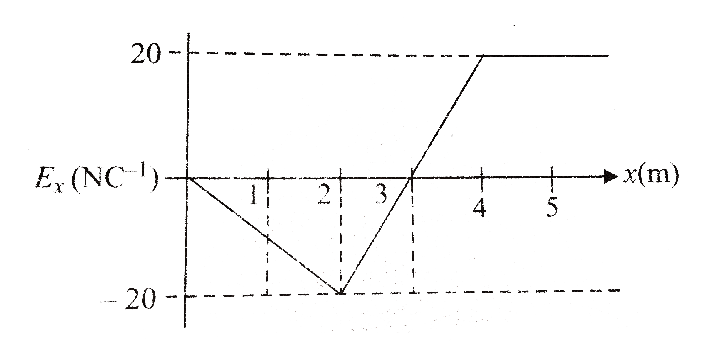
View SolutionA graph of the x-component of the electric field as a function of x in a region of space is shown in figure. The y−andz−compo≠nts of the electric field are zero in this region. If the electric potential is 10 V at the origin, then the potential at x = 2.0 m is
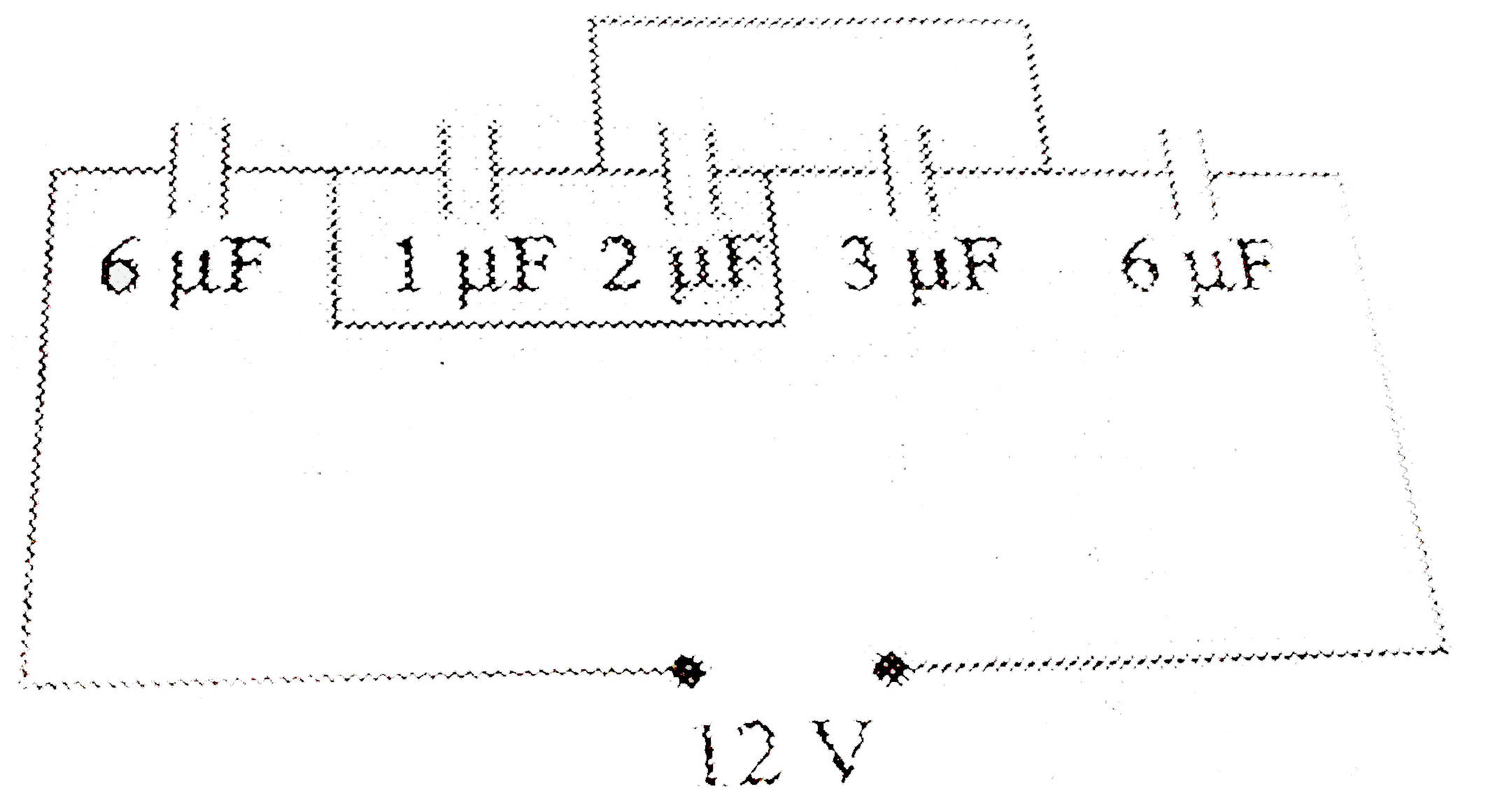
View SolutionFigure shows five capacitors connected across a 12V power supply. What is the charge on the 2μF capacitor ?
View SolutionFigure shows part of a circuit. Which points have the same potential as that of point a

View Solution

