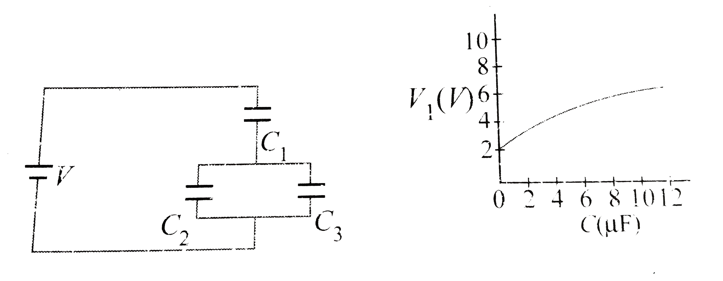
Capacitor 3 in Fig. 25-40a is a variable capacitor (its capacitance C3 can be varied) Figure 25-40b gives the electric potential V1 across capacitor 1 versus C3 The horizontal scale is set by C3s=12.0μF Electric potential V1 approaches as asymptote of 8.0 V as C3→∞ What are (a) the electric potential V across the battery , (b) C1 and (c) C2?
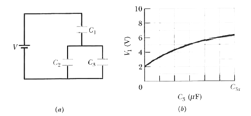
a)8.0Vb)4.5μFc)1.5μF
Topper's Solved these Questions
- CAPACITANCEBOOK - RESNICK AND HALLIDAYCHAPTER - CAPACITANCEEXERCISE - PRACTICE QUESTIONS (SINGLE CORRECT CHOICE TYPE)
23 Videos
- CAPACITANCEBOOK - RESNICK AND HALLIDAYCHAPTER - CAPACITANCEEXERCISE - PRACTICE QUESTIONS (MORE THAN ONE CORRECT CHOICE TYPE)
12 Videos
- CAPACITANCEBOOK - RESNICK AND HALLIDAYCHAPTER - CAPACITANCEEXERCISE - CHECKPOINTS
4 Videos
- ALL ABOUT ATOMS BOOK - RESNICK AND HALLIDAYCHAPTER - ALL ABOUT ATOMS EXERCISE - CHECKPOINT
1 Videos
- CENTER OF MASS BOOK - RESNICK AND HALLIDAYCHAPTER - CENTER OF MASS EXERCISE - Practice Questions (Integer )
4 Videos
Similar Questions
Capacitor C3 in the circuit is variable capacitor (its capacitance can be varied). Graph is plotted between potential difference V1 (across capacitor C1) versus C3.
Electric potential V1 approaches on asymptote of 10 volts as C3→∞
The ratio of the capacitance C1C2 will be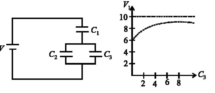
View SolutionCapacitor C3 in the circuit is variable capacitor (its capacitance can be varied). Graph is plotted between potential difference V1 (across capacitor C1) versus C3.
Electric potential V1 approaches on asymptote of 10 volts as C3→∞
0The value of C3 for which potential difference across C1 will become 8V, is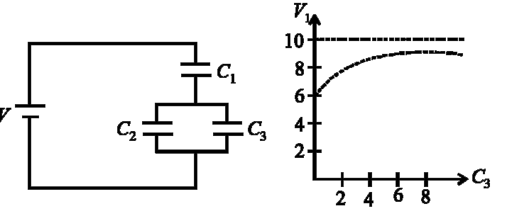
View Solution
Knowledge Check
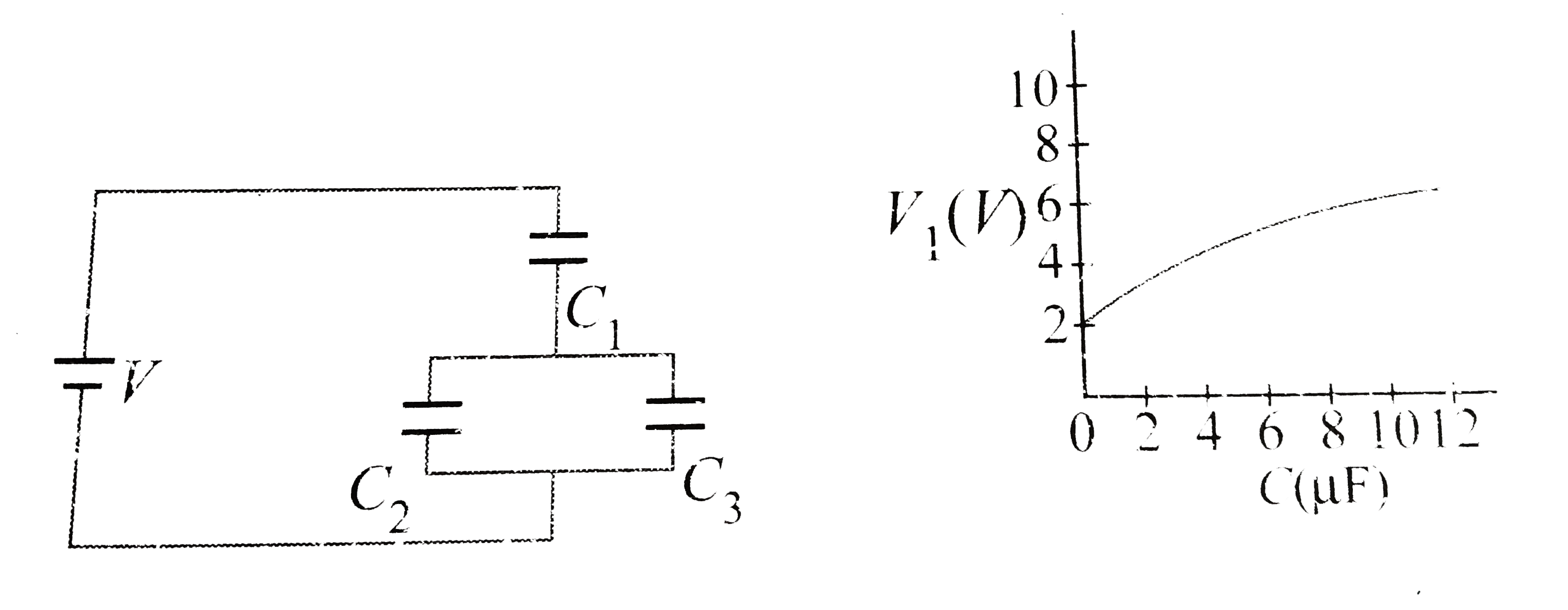
Capacitor C3 in the circuit is a variable capacitor (its capacitance can be varied). C1andC2 are of fixed values. Graph is plotted between potential difference V1 (across capacitor C1) versus C3. Electric potential V1 approches on asymptote of 10 V as C3∝∞.
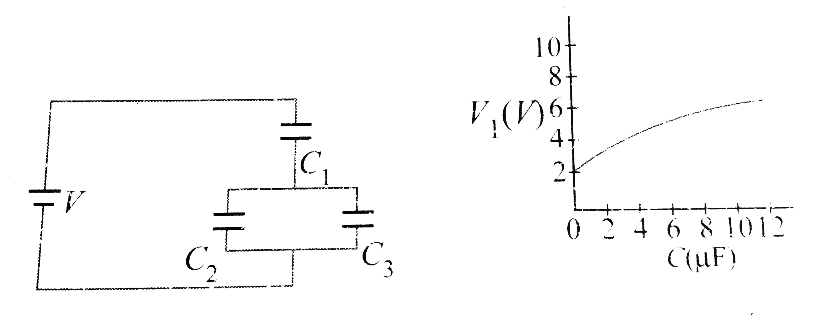 ,
,
The electric potential V across the battery is equal toA10VB12VC16VD20VCapacitor C3 in the circuit is a variable capacitor (its capacitance can be varied). C1andC2 are of fixed values. Graph is plotted between potential difference V1 (across capacitor C1) versus C3. Electric potential V1 approches on asymptote of 10 V as C3∝∞.
 ,
,
When V1=4Vm then C3 is equal toA5C2/2B5C1/3C5C2/3Dnone of theseCapacitor C3 in the circuit is a variable capacitor (its capacitance can be varied). C1andC2 are of fixed values. Graph is plotted between potential difference V1 (across capacitor C1) versus C3. Electric potential V1 approches on asymptote of 10 V as C3∝∞.
 ,
,
Relation between C1andC2 isAC1=C2BC1=4C2C4C1=C2Dany relation
Capacitor C3 in the circuit is variable capacitor (its capacitance can be varied). Graph is plotted between potential difference V1 (across capacitor C1) versus C3.
Electric potential V1 approaches on asymptote of 10 volts as C3→∞
The ratio of energy stored in capacitorC1 to that of total energy whenC3→∞ is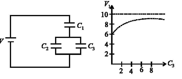
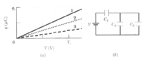
View SolutionPlot 1 in fig25-42a gives the charge q that can be stored on capacitor 1 versus the electric potential V set up across it. The vertical scale is set by qs=16.0μF and the horizontal scale is set by VS=2.0V Plots 2 and 3 are similar plots for capacitors 2 and 3 respectively. FIgure 25-42b shows a circuit that whose three capacitors and a 10.0V battery.What is the charge stored on capacitor 2 in that circuit?
View SolutionCapacitor C3 in the circuit is a veriable capacitor (its capacitance can be varied). Group is plotted between potential difference V1 (across capacitor C1) versus C3. Electric potential V1 approaches to 10 V as C3→∞. Given that C1+C2=10μF

The capacitance of the capacitor C1 value
View SolutionCapacitor C3 in the circuit is a veriable capacitor (its capacitance can be varied). Group is plotted between potential difference V1 (across capacitor C1) versus C3. Electric potential V1 approaches to 10 V as C3→∞. Given that C1+C2=10μF

EMF of the battery is equal to
View SolutionA capacitor of capacitance C is charged to a potential V. The flux of the electric field through a closed surface enclosing the capacitor is
View Solution
