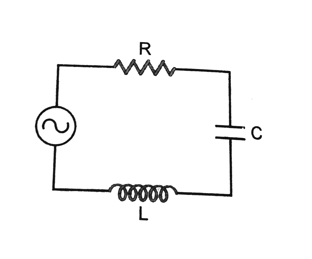
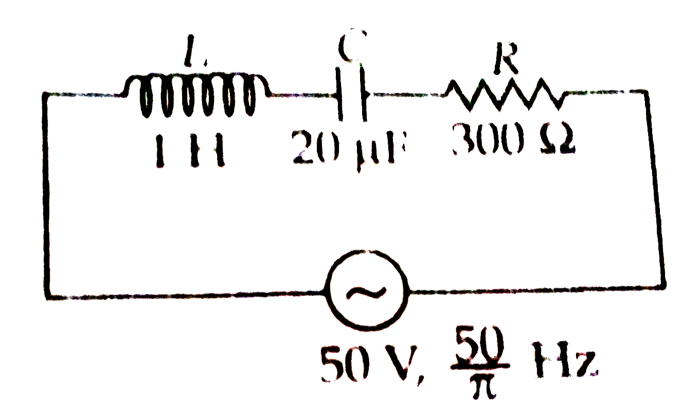
A series LCR circuit is shown in the figure below.

Determine the source frequency which drives the circuit in resonance . Also obtain the value of Q - factor of the circuit.
Let ωr be the resonance frequency
ωr=1√LC=1√80×10−3×50×10−6=500 rad /s
∴Fr=ωr2π=5002π=80Hz
Q - factor is Q=ωrLR=500×80×10−360=23=0.67
Topper's Solved these Questions
- ALTERNATING CURRENT BOOK - MODERN PUBLICATIONCHAPTER - ALTERNATING CURRENT EXERCISE - PRACTICE PROBLEMS
67 Videos
- ALTERNATING CURRENT BOOK - MODERN PUBLICATIONCHAPTER - ALTERNATING CURRENT EXERCISE - CONCEPTUAL QUESTIONS
25 Videos
- ATOMS BOOK - MODERN PUBLICATIONCHAPTER - ATOMS EXERCISE - Chapter Practice Test
16 Videos
Similar Questions
A series LCR circuit with L=80mH,C=50μF and R=60ohm is connected to a variable frequency 220 V source. Determine (i) the source frequency which drives the circuitin resonance (iii) the quality factor Q of the circuit.
View SolutionA series LCR circuit connected to a variable frequency 230 V source has L = 5.0 H, C=80μF, R=40Ω, Fig.
(a) Determine the source frequency which drives the circuit in resonance.
(b) Obtain the impedance of the circuit and amplitude of current at at resonating frequency.
(c ) Determine the r.m.s. potential drops acorss the three elements the circuits. Show that the potential drop acorss the LC combination is zero at the resonating frequecny.
View Solution
Knowledge Check
In LCR circuit as shown in figure
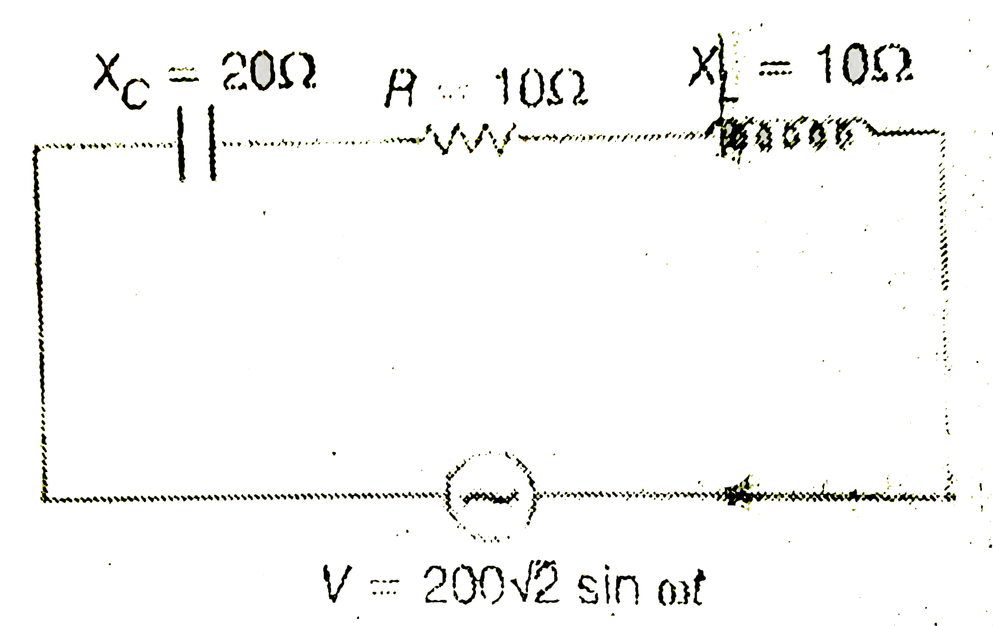 Acurrent will lead the voltageBrms value of current is 20ACpower factor of circuit is 1√2Dvoltage drop across resistance is 100V
In series LCR circuit at resonance
APower factor is zeroBPower developed across the resistor is maximumCPower developed across the inductor is zeroDBoth (2) & (3)In series LCR circuit at resonance,
Acurrent is maximum and impedance is maximumBcurrent is maximum and impedance is minimumCcurrent is minimum and impedance is maximumDcurrent is minimum and pmpedance is minimum
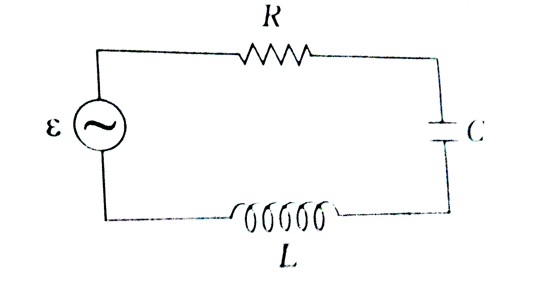
Figure here, shows a series L-C-R circuit connected to a variable frequency 230 V source. L = 5.0H, C = 80μF and r =40Ω
(a) Determine the source frequency which drives the circuit in resonance.
(b) Obtain the impedance of the circuit and the amplitude of current at the resonating frequency.
(c) Determine the rms potential drops across the three elements of the circuit. show that the potential drop across the L-C combination is zero at the resonating frequency.
View SolutionIn the series LCR circuit shown, the impedance is
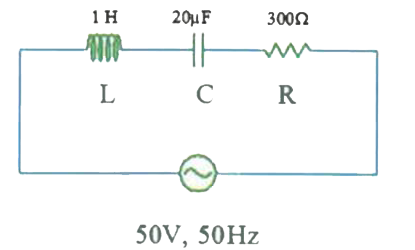
View SolutionIn the series LCR circuit shown, the impedance is

View SolutionIn series LCR circuit at resonance,
View SolutionIn the series LCR circuit shown the impedance is
View Solution
