In LCR circuit as shown in figure
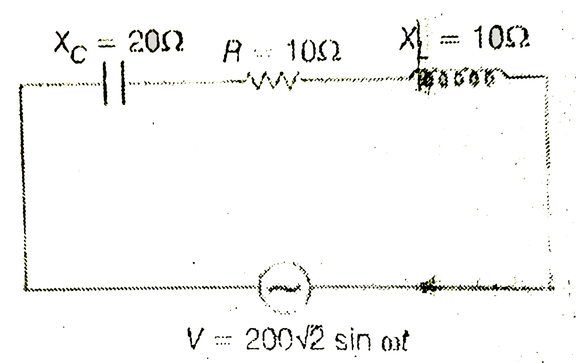
current will lead the voltage
rms value of current is 20A
power factor of circuit is 1√2
voltage drop across resistance is 100V
The correct Answer is:A, C
Step by step video, text & image solution for In LCR circuit as shown in figure by Physics experts to help you in doubts & scoring excellent marks in Class 12 exams.
Updated on:21/07/2023Similar Questions
Knowledge Check
In LCR circuit shown in figure, then choose incorrect option:
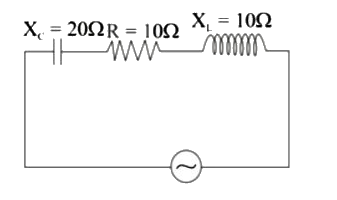 ACurrent will lead the voltageBrms value of current is 20 ACPower factor of the circuit is 1√2DVoltage drop across resistance = voltage drop across inductor
In the LCR circuit shown in figure
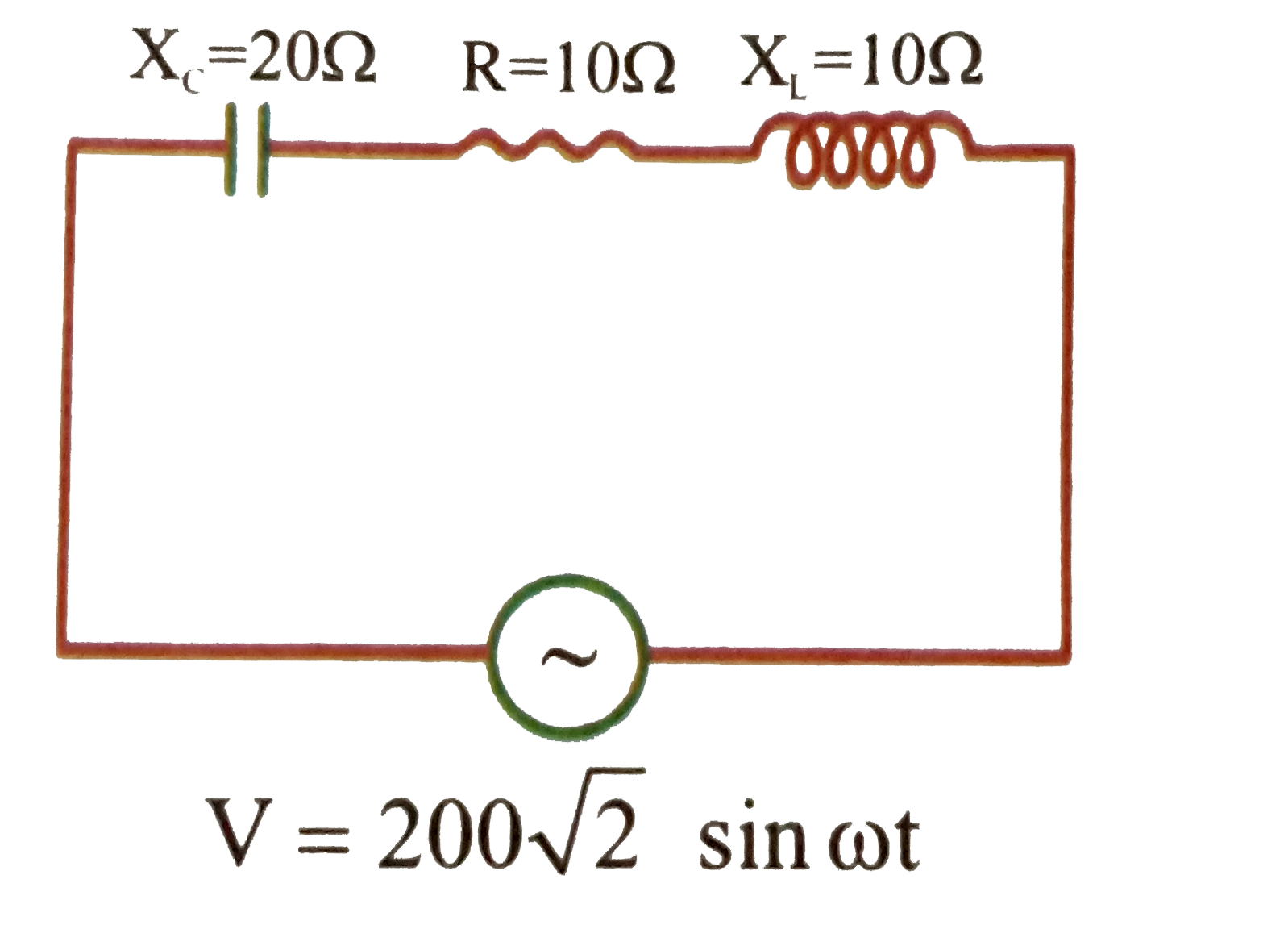
(a) current will lead the voltage
(2) rms value of current in 20A
(3) power factor of the circuit is 1√2
(4) voltage drop across resistance is 100VA(1) and (3) are correctB(1) and (4) are correctC(2) and (3) are correctD(3) and (4) are correctIn the circuit as shown in figure the
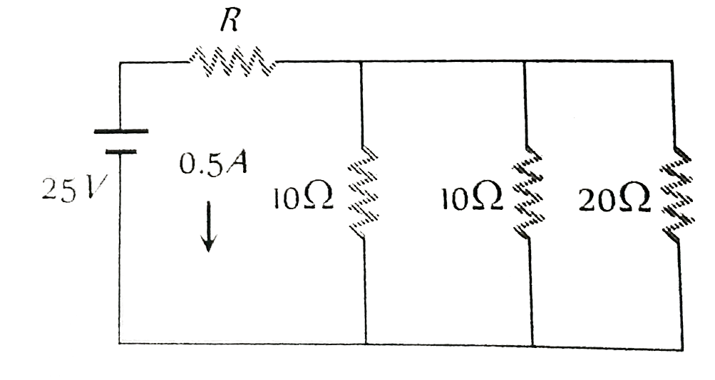 AResistance R=46ΩBCurrent through 20Ω resistance is 0.1ACPotential difference across the middle resistance is 2VDAll option are correct
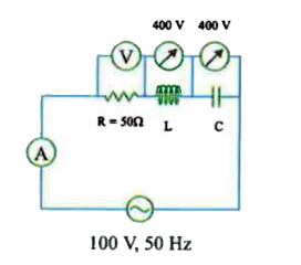
In the series LCR circuit as shown in the figure, the voltmeter V and ammeter A reading are
View SolutionFor the sereis LCR circuit shown in figure, the resonating frequency and current amplitude at resonance respectivley are
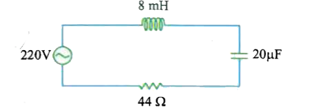
View SolutionFor the sereis LCR circuit shown in figure, the resonating frequency and current amplitude at resonance respectivley are

View SolutionA series LCR circuit is shown in the figure below.

Determine the source frequency which drives the circuit in resonance . Also obtain the value of Q - factor of the circuit.
View Solution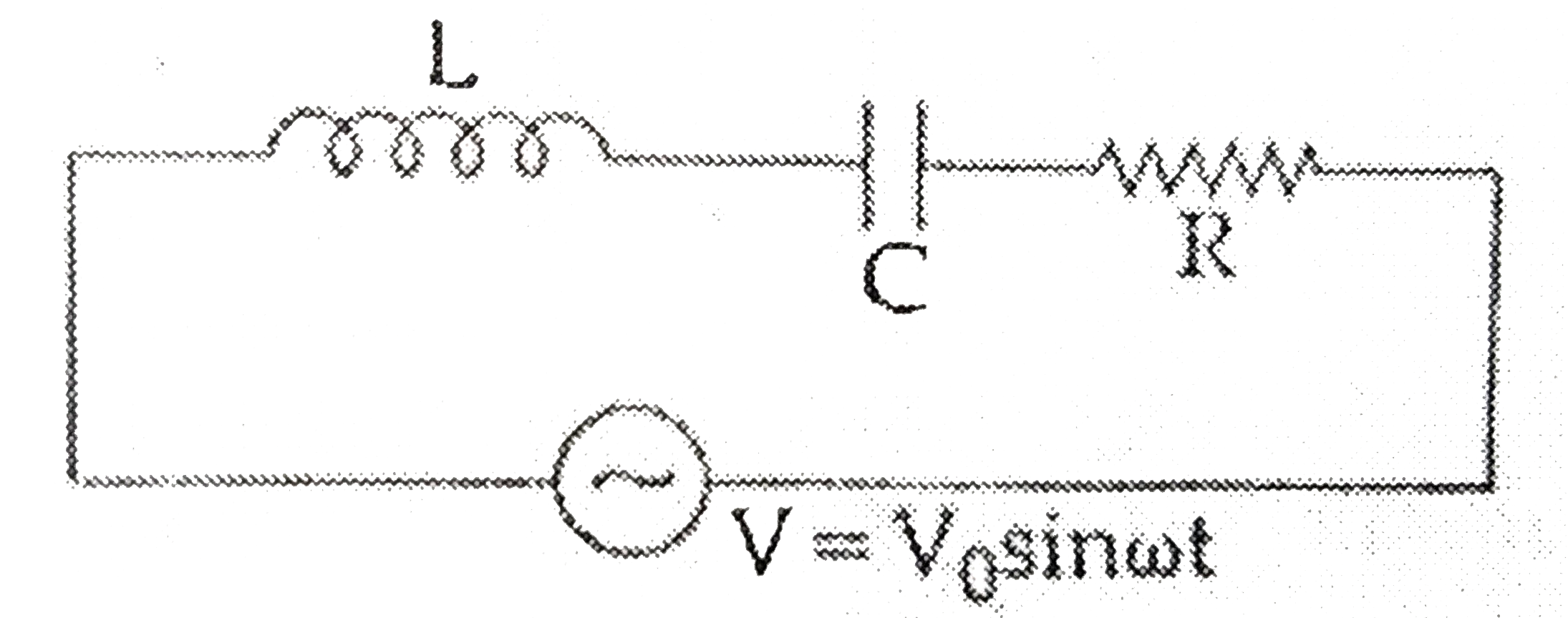
The current in the LCR circuit shown in the figure is observed to lead the voltage in phase. Without making any other change in the circuit, a capacitor, of capacitance C0 is (appropriately) joined to the capacitor C. This results in making the current, in the joined to the capacitor C. This results in making the current, in the modified' circuit, flow in phase with the applied voltage.
Draw a diagram of the modified circuit and obtain an expression of C0 in terms of Ω, L and C.
View Solution
