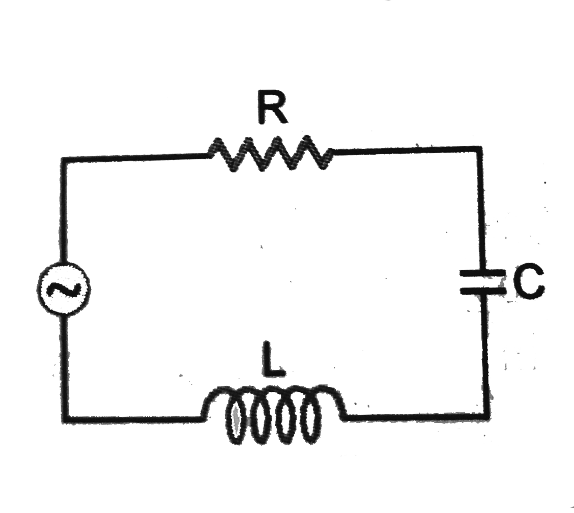
A series LCR circuit with L=80mH,C=50μF and R=60ohm is connected to a variable frequency 220 V source. Determine (i) the source frequency which drives the circuitin resonance (iii) the quality factor Q of the circuit.
To solve the problem step by step, we will first determine the source frequency that drives the circuit in resonance and then calculate the quality factor Q of the circuit.
Given Data:
- Inductance, L=80mH=80×10−3H
- Capacitance, C=50μF=50×10−6F
- Resistance, R=60Ω
- RMS Voltage, VRMS=220V
Step 1: Calculate the Resonant Frequency
At resonance, the inductive reactance XL equals the capacitive reactance XC. The resonant frequency f can be calculated using the formula:
f=12π√LC
Calculation:
1. Calculate LC:
LC=(80×10−3)×(50×10−6)=4×10⁻⁶H⋅F
2. Calculate √LC:
√LC=√4×10−6=2×10⁻³s
3. Calculate the resonant frequency f:
f=12π(2×10⁻³)≈10.012566≈79.58Hz
Step 2: Calculate the Quality Factor Q
The quality factor Q of the circuit can be calculated using the formula:
Q=ω0LR
Where ω0=2πf.
Calculation:
1. Calculate ω0:
ω0=2πf=2π(79.58)≈500rad/s
2. Substitute ω0, L, and R into the Q formula:
Q=500×(80×10−3)60
3. Calculate Q:
Q=4060≈0.67
Final Answers:
- (i) The source frequency which drives the circuit in resonance is approximately 79.58 Hz.
- (ii) The quality factor Q of the circuit is approximately 0.67.
- Inductance, L=80mH=80×10−3H
- Capacitance, C=50μF=50×10−6F
- Resistance, R=60Ω
- RMS Voltage, VRMS=220V
At resonance, the inductive reactance XL equals the capacitive reactance XC. The resonant frequency f can be calculated using the formula:
1. Calculate LC:
LC=(80×10−3)×(50×10−6)=4×10⁻⁶H⋅F
√LC=√4×10−6=2×10⁻³s
f=12π(2×10⁻³)≈10.012566≈79.58Hz
The quality factor Q of the circuit can be calculated using the formula:
1. Calculate ω0:
ω0=2πf=2π(79.58)≈500rad/s
Q=500×(80×10−3)60
Q=4060≈0.67
- (i) The source frequency which drives the circuit in resonance is approximately 79.58 Hz.
- (ii) The quality factor Q of the circuit is approximately 0.67.
Topper's Solved these Questions
- ELECTROMAGNETIC INDUCTION & ALTERNATING CURRENTBook:PRADEEPChapter:ELECTROMAGNETIC INDUCTION & ALTERNATING CURRENTExercise:Solved Examples (b)
Explore 1 Video
- ELECTROMAGNETIC INDUCTION & ALTERNATING CURRENTBook:PRADEEPChapter:ELECTROMAGNETIC INDUCTION & ALTERNATING CURRENTExercise:Short Answer Qusetions
Explore 2 Videos
- DUAL NATURE OF RADIATION AND MATTERBook:PRADEEPChapter:DUAL NATURE OF RADIATION AND MATTERExercise:Exercise
Explore 191 Videos
- ELECTROMAGNETIC WAVESBook:PRADEEPChapter:ELECTROMAGNETIC WAVESExercise:II Focus multiple choice question
Explore 5 Videos
Similar Questions
A series LCR circuit with L=4.0h,C=100μF and R=60Ω is connected to a varialbe frequency 240 V source. Calcalate
(i) angular frequency of the source which drives the circuit in resonace,
(ii) current at the resonating frequency,
(iii) rms potential drop across the inductro at resonance.
View SolutionFig. shows series LCR circuit with L=5.0H,C=80μF,R=40Ω connected to a variable frequency 240 V source. Calculate
(i) the angular freuquency of the source which drives the circuit at resonance.
(ii) Current at the resonanting frequency.
(iii) the rms pot. drop across the capacitor at resonance.

View Solution
Knowledge Check
Figure shows a series LCR circuit connected to a variable frequency 230 V source.

The source frequency which drives the circuit the circuit in resonance isA4 HzB5 HzC6 HzD8 Hz
A series LER circuit with C=80μF, L = 5.0 H and R=40Ω is connected to a variable frequency 240 V a.c. source Calculate
(i) angular frequency of the source which drives the circuit in resonanace.
(ii) current at the resonating frequency.
(iii) rms pot. drop across the capacitor.
View SolutionThe figure shows a series LCR circuit with L=10.0H2,C=40μF,R=60Ω connected to a variable frequency 240 V source. Calculate
(i) The angular frequency of the source which drives the circuit at resonance.
(ii) The current at the resonating frequency.
(iii) The rms potential drop across the capacitor at resonance.

View SolutionA series LCR circuit is shown in the figure below.

Determine the source frequency which drives the circuit in resonance . Also obtain the value of Q - factor of the circuit.
View SolutionA series L-C-R circuit with R=44Ω,C=8μFandL=50H is connected to a variable frequency 220 V ac suppy. Calculate angular frequency, impedance and current at resonance condition.
View SolutionA series LCR circuit connected to a variable frequency 230 V source has L = 5.0 H, C=80μF, R=40Ω, Fig.
(a) Determine the source frequency which drives the circuit in resonance.
(b) Obtain the impedance of the circuit and amplitude of current at at resonating frequency.
(c ) Determine the r.m.s. potential drops acorss the three elements the circuits. Show that the potential drop acorss the LC combination is zero at the resonating frequecny.

View SolutionFigure here, shows a series L-C-R circuit connected to a variable frequency 230 V source. L = 5.0H, C = 80μF and r =40Ω
(a) Determine the source frequency which drives the circuit in resonance.
(b) Obtain the impedance of the circuit and the amplitude of current at the resonating frequency.
(c) Determine the rms potential drops across the three elements of the circuit. show that the potential drop across the L-C combination is zero at the resonating frequency.

View SolutionA series LCR circuit with R=20Ω,L=1.5H and C=35μF is connected to a variable frequency 200V ac supply. When the frequency of the supply equals the natural frequency of the circuit, what is the average power in Kw transferred to the circuit in one complete cycle?
View Solution

