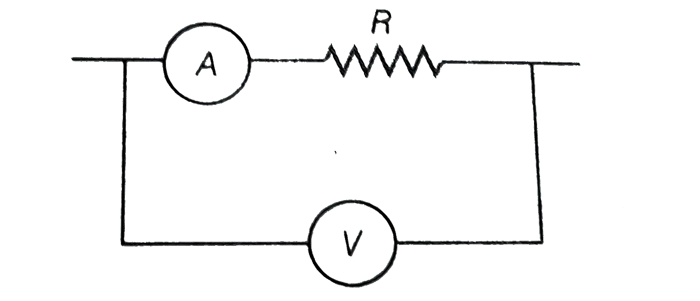
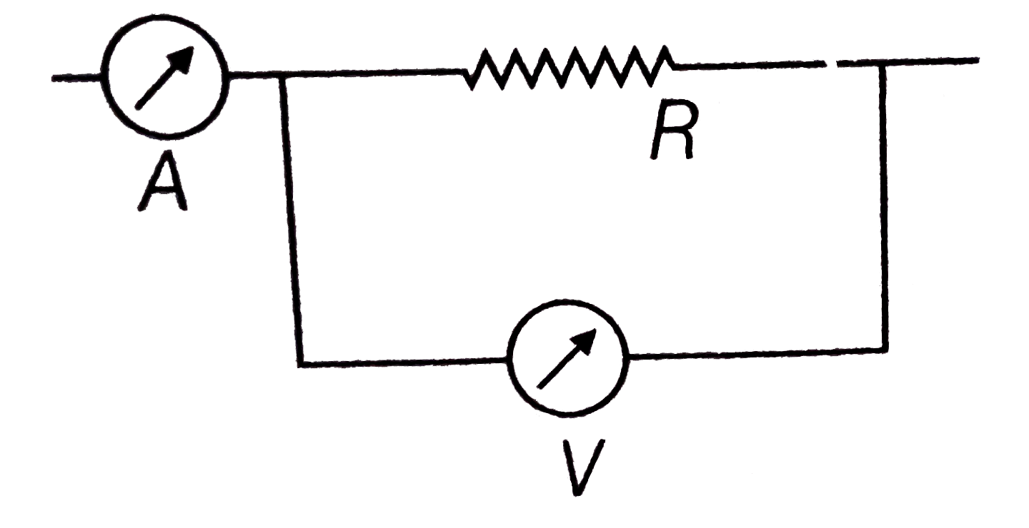
In the circuit shown the reading of ammeter and voltmeter are 4A and 20V respectively. The meters are non ideal, then R ia

5Ω
less than 5Ω
greater than 5Ω
between 4Ω and 5Ω
The correct Answer is:C
Step by step video, text & image solution for In the circuit shown the reading of ammeter and voltmeter are 4 A and 20 V respectively. The meters are non ideal, then R ia by Physics experts to help you in doubts & scoring excellent marks in Class 12 exams.
Updated on:21/07/2023Topper's Solved these Questions
- CURRENT ELECTRICITYBOOK - RESONANCECHAPTER - CURRENT ELECTRICITYEXERCISE - Exercise-2 (Part-2)
16 Videos
- CURRENT ELECTRICITYBOOK - RESONANCECHAPTER - CURRENT ELECTRICITYEXERCISE - Exercise-2 (Part-3)
22 Videos
- CURRENT ELECTRICITYBOOK - RESONANCECHAPTER - CURRENT ELECTRICITYEXERCISE - Exercise-1 (Part-3)
2 Videos
- COMMUNICATION SYSTEMSBOOK - RESONANCECHAPTER - COMMUNICATION SYSTEMSEXERCISE - Exercise 3
13 Videos
- DAILY PRACTICE PROBLEMBOOK - RESONANCECHAPTER - DAILY PRACTICE PROBLEMEXERCISE - DPP.No.71
1 Videos
Similar Questions
Knowledge Check
In the circuit shown here, the readings of the ammeter and voltmeter are
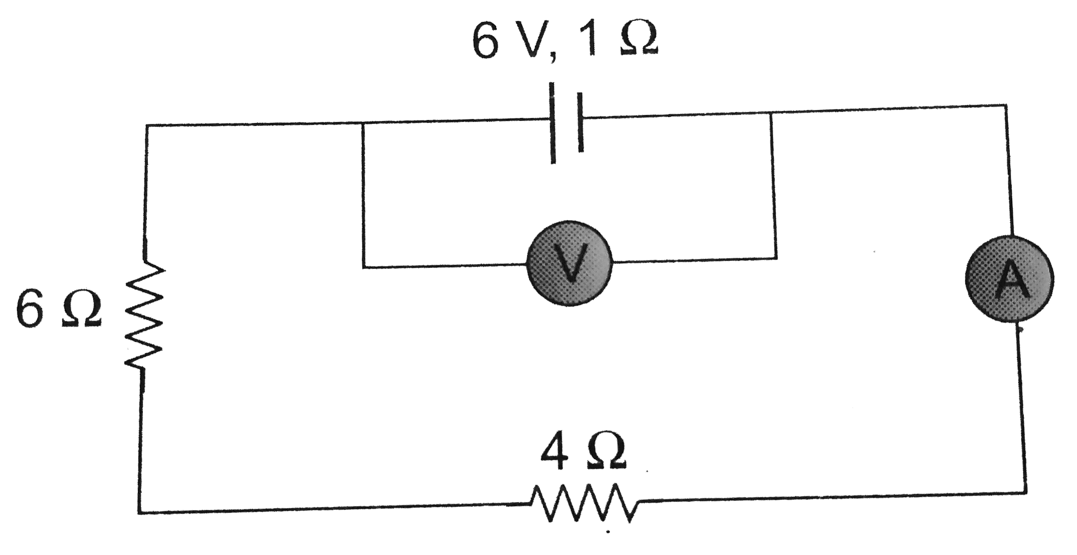 A6A,60VB0.6A,6VC6/11A,60/11VD11/6A,11/60V
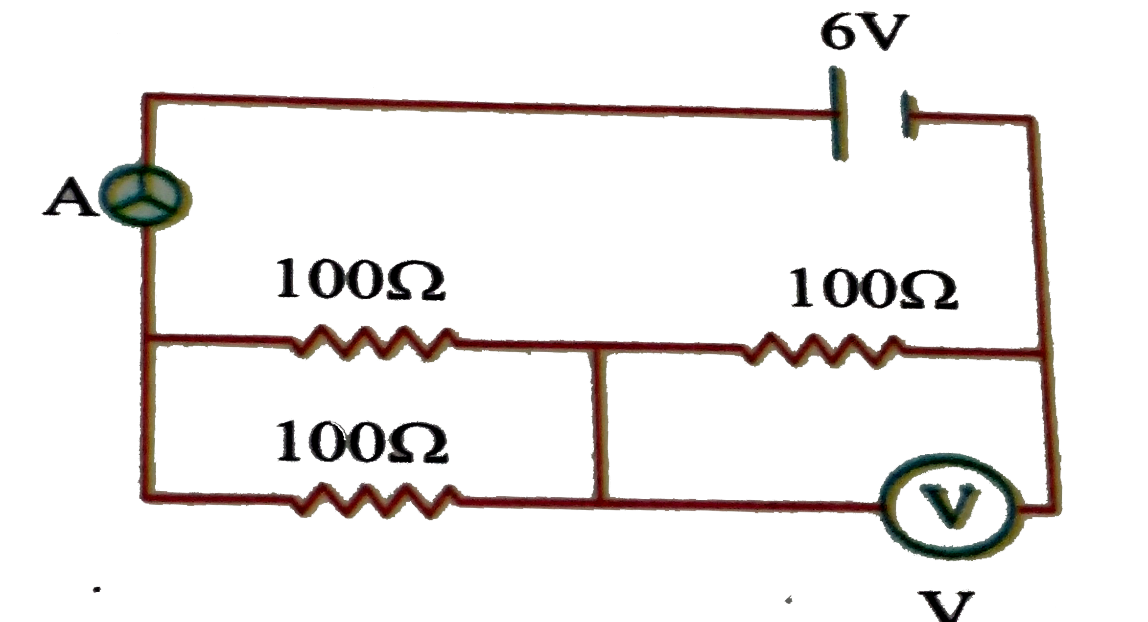
In the circuit shown, the reading of the voltmeter and the ammeter areA4V.0.2AB2V,0.4AC3V,0.6AD4V,0.04AFor the AC circuit shown, the reading of ammeter and voltmeter are 5A and 50√5 volts respectively, then
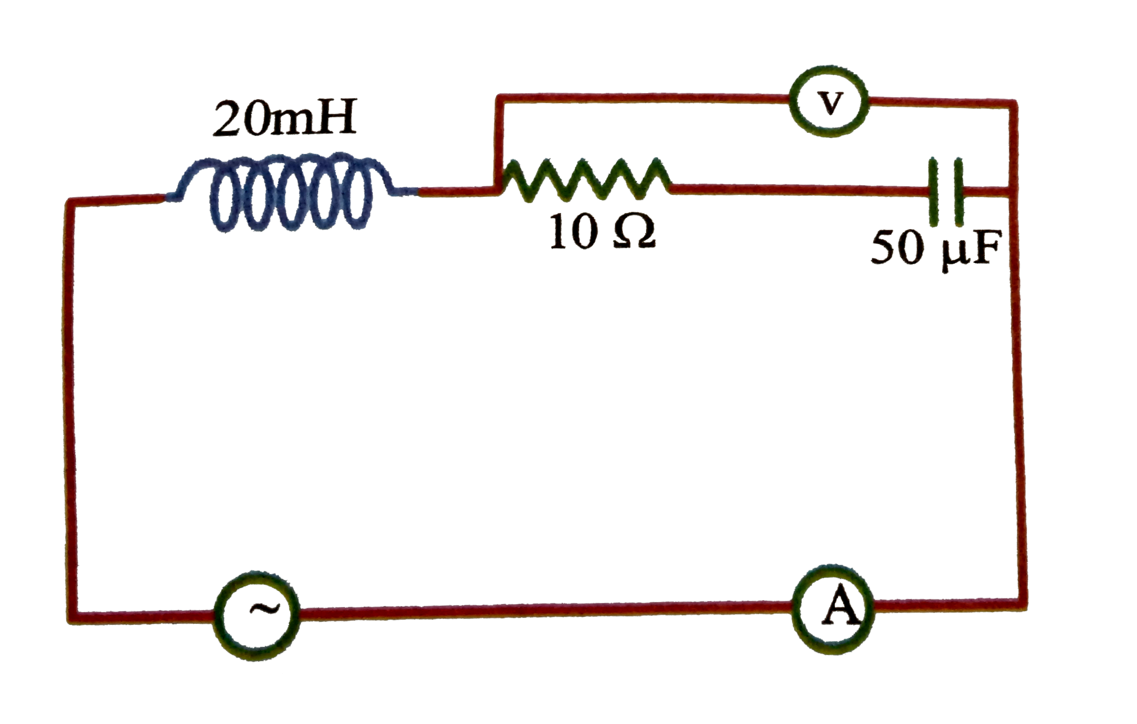 Aaverage power deliverd by the source is 250WBrms value of AC source is 50 voltsCvoltage gain is 2Dfrequency of ac source is 1000rad/s
In the adjoining circuit diagram, the readings of ammeter and voltmeter are 2 A and 120 V, respectively. If the value of R is 75Ω, then the voltmeter resistance will be
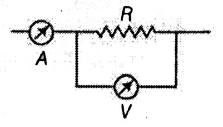
View SolutionFor the adjoining circuit diagram, the readings of ammeter and voltmeter are 2A and 120 V respectively. If the value of R is 75Ω, then the voltmeter resistance will be
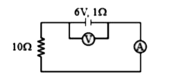
View SolutionFind the readings of the ammeter (A) and voltmeter (V):
View SolutionThe reading of ammeter and voltmeter in the following circuit are respectively
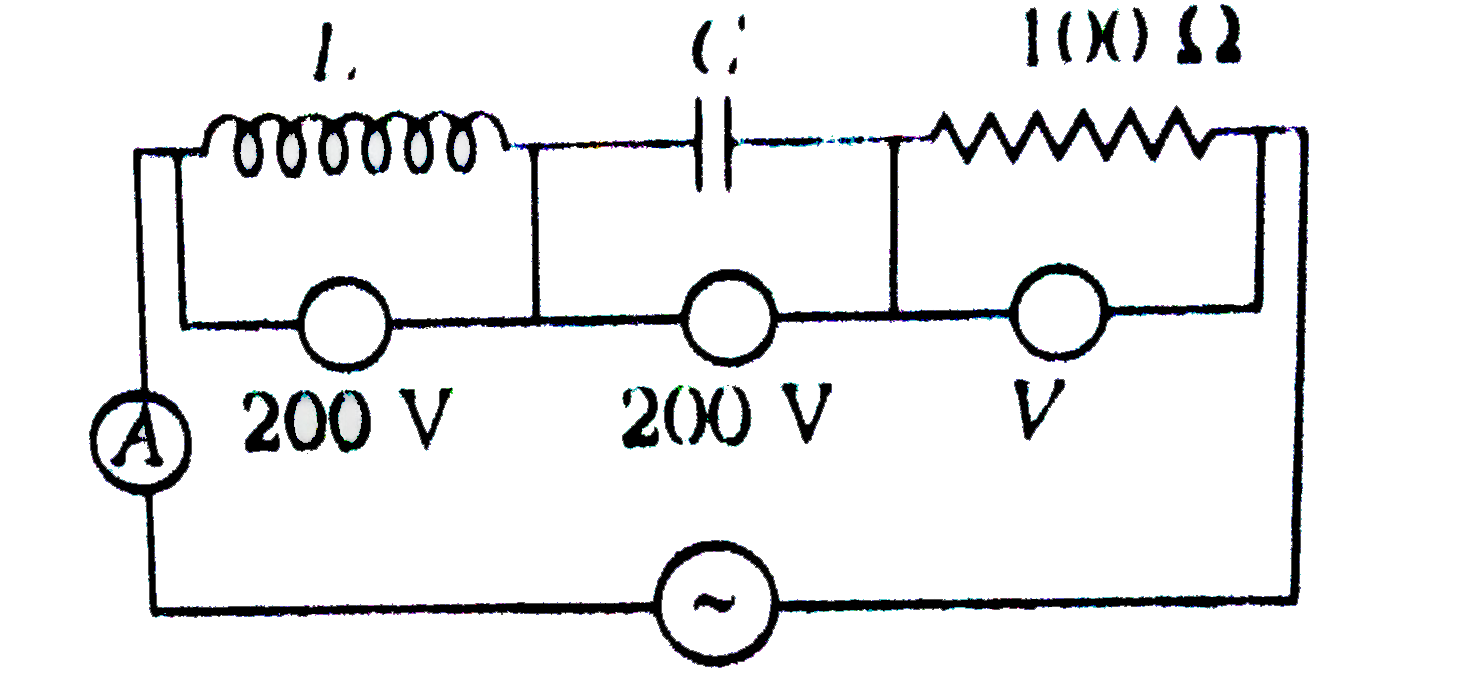
View SolutionIn the circuits shown below, the readings of the voltmeters and the ammeters will be
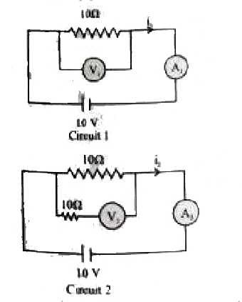
View Solution


