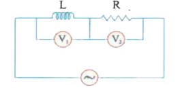
A pure inductor and a pure resistor are connected in series and an ac supply is connected across this combination. Ideal ac volt meters v1 and v2 show 120 volt and 160 volt respectively . What is the phase difference between V1 and V2.

Step by step video & image solution for A pure inductor and a pure resistor are connected in series and an ac supply is connected across this combination. Ideal ac volt meters v_(1) and v_(2) show 120 volt and 160 volt respectively . What is the phase difference between V_(1) and V_(2). by Physics experts to help you in doubts & scoring excellent marks in Class 12 exams.
Similar Practice Problems
- Question 1 - Select One
A resistor an inductor and a capacitor are connected in series to an ac source An ac voltmeter measures the votage across them as 800V,30V and 90V respectively The rms value of the supply voltage is .
A100VB100√2VC200VD200√2V - Question 1 - Select One or More
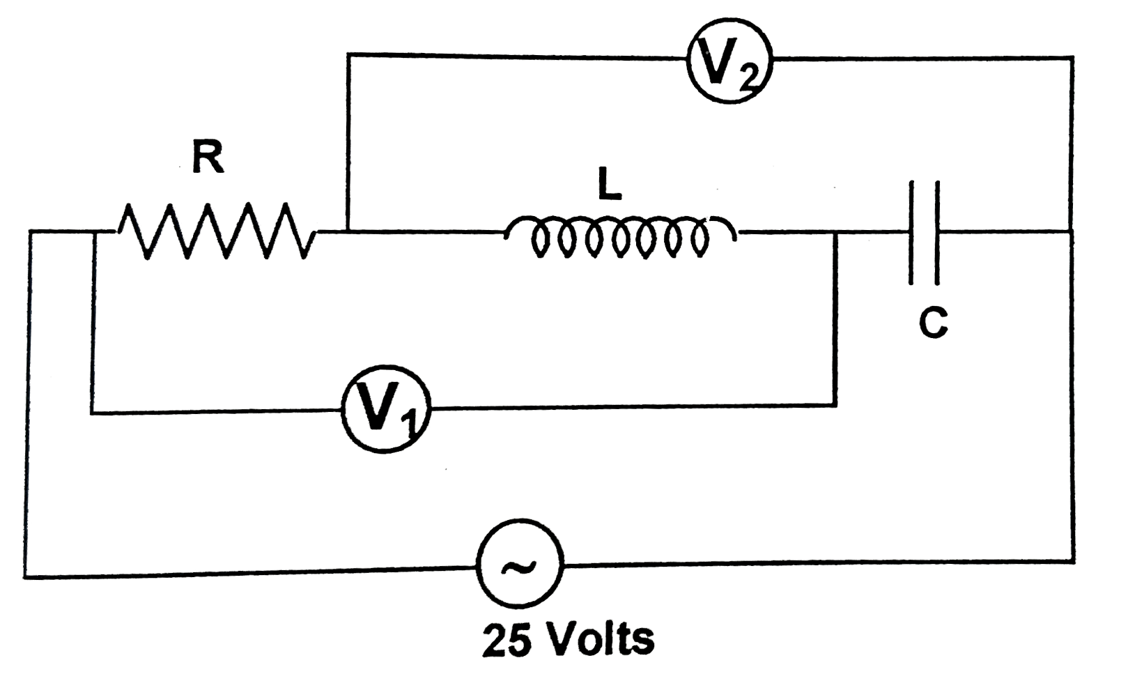
In an LCR series circuit, the reading of ideal voltmeters V1 and V2 are 20√2 volt and 15 volts respectively as shown in the figure (the given circuit in inductive in nature). Then
 AThe voltage across resistor is 20 voltsBThe voltage across inductor is 20 voltsCThe voltage across capacitor is 5 voltsDThe power factor of the circuit is 45
 - Question 1 - Select One
An ideal inductor of (1/π) is connected in series with a 300γ resistor If a 20V.200Hz ac source is connected across the combination the phase difference between the voltage and the current is .
Atan−54Btan−145Ctan−134Dtan−143 - Question 1 - Select One
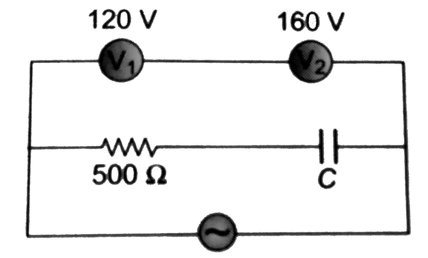
A 500Ω resistor and a capacitor C are connected in series across 50HzAC supply mains. The r.m.s potential difference recorded on voltmeter V1 and V2 are V1=120V and V2=160V. The power taken for the mains is:
 A480WB240WC28.8WD14.4W
 - Question 1 - Select One
Consider the circuit shown in the figure, the cell is ideal. The readings of the ideal voltmeters V1 and V2 in volts are respectively.
 A2,0B0,2C0,0D2,2
Similar Questions
In a series L–C–R circuit, voltages across inductor, capacitor, and resistor are VL,VCandVR respectively. What is the phase difference between (i) VLandVR (ii) VLandVC ?
View SolutionA resistor and a capacitor are connected in series with an a.c. source. If the potential drop across the capacitor is 5 V and that across resistor is 12 V, applied voltage is
View SolutionA 200 mH (pure) inductor and a 5uF (pure) capacitor are connected, one by one, across a sinusoidal a.c. voltage source V= 70.7 sin (1000 t) volts. Obtain the expression for the current in each case.
View SolutionIn a series LCR circuit, the voltage across an inductor, a capacitor and a resistor are 20 V, 20 V and 40 V, respectively. What is the phase difference between the applied voltage and the current in the circuit ?
View SolutionIn a series LCR circuit, the voltages across an inductor, a capacitor and a resistor are 30 V, 30 V, 60 V respectively. What is the phase difference between the applied voltage and the current in the circuit ?
View Solution

