Derive an expression for the impedance of a series LCR, circuit, when an AC voltage is applied to it.Solution in Kannada
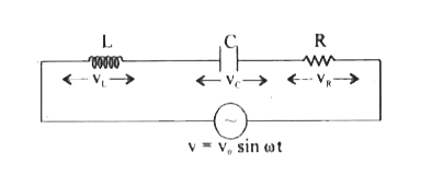
Consider a resistance R, an inductor of self inductance L and a capacitor of capacitance C connected in series across an AC source.The applied voltage is given by, v=v0sinωt …(1)

where, v0 is the instantaneous value, v. is the peak value and ω=2πf, f being the frequency of AC.
If i be the instantaneous current at time t, the instantaneous voltages across R, L and Care respectively iR, iXL and iXC. The vector sum of the voltage amplitudes across R, L, C equals the amplitude v0 of the voltage applied.
Let vR,vL and vC be the voltage amplitudes across R, L and C respectively and I0 the current amplitude.
Then vR=i0R is in phase with i0.
vL=i0XL=i0(ωL) leads i0 by 90∘
vc=i0XC=i0(1ωC) lags behind i0 by 90∘ .

The current in a pure resistor is phase with the voltage, whereas the current in a pure inductor lags the voltage by π2 rad. The current in a pure capacitor leads the voltage by π2 rad. For VL>VC, phase angle ϕ between the voltage and the current is positive.
From the right angled triangle OAP,
OP2=OA2+AP2=OA2+OB2(∵AP=OB)
=v2R+(vL−vC)2
=(iR)2+(iXL−iXC)2
=i2(R2+(XL−XC)2)
∴i=v√R2+(XL−XC)2=vZ
and Z=√R2+(XL−XC)2
Where Z is the impedance of the circuit
Phase angle between v & i.
tanϕ=vL−vCvR=XL−XCRL
ϕ=tan−1(XL−XCR)
Topper's Solved these Questions
Similar Questions
A spherical hollow conductor is charged to -250V. If the radius of the conductor is 0.15m, then calculate
(i) Charge on the conductor.
(ii) Electric files intensity on the surface
(iii) Electric field intensity at the centre.
(iv) Electric potential difference between A and B at distances of 0.20 m & 0.25m from the centre respectively.
View SolutionFor a short magnetic dipole of magnetic moment 0.5 Am2. Find the magnetic field at a point ( a) 1 m on the axis and from the cetre of the magnet ( dipole ) ( b) 1 m on the equatorial line from the centre ( c) at an angle of 60∘ w.r. to the line joining the point and the centre of the dipole at distance 1 m.
View SolutionSketch a graph showing the variation of impedance of LCR circuit the frequency of applied voltage.
View Solutionप्रत्यावर्ती वोल्टता स्रोत के साथ सम्बद्ध श्रेणी LCR परिपथ के लिए फेजर चित्र खींचते हुए परिपथ की प्रतिबाधा का व्यंजक ज्ञात करें।
View SolutionObtain on expression for impedance and current in series LCR circuit. Deduce an expression for the resonating frequency of an LCR series reasonating circuit.
View SolutionWhen the frequency of AC is doubled, the impedance of an LCR, circuit is
View SolutionWhen the frequency of the ac voltage applied to a series LCR circuit is gradually increased from a low value , the impedance of the circuit.
View Solutionश्रेणी LCR परिपथ में वोल्टता और धारा कब समान कला में होती हैं ?
अथवा
श्रेणी LCR परिपथ में प्रतिबाधा कब पूर्णतः ओमीय होती है ?
View Solutionश्रेणी LCR परिपथ की प्रतिबाधा के लिए व्यंजक लिखिए।
View SolutionWhen the frequency of AC is doubled, the impedance of an LCR series circuit
View SolutionAlternating Current | AC Voltage Applied To A Series LCR Circuit
View SolutionDerive an expression for the impedance of a series LCR, circuit, when an AC voltage is applied to it.
View SolutionDerive an expression for the impedance of a series LCR, circuit, when an AC voltage is applied to it.
View SolutionObtain the relation of voltage applied to a series LCR circuit.
View SolutionWhen the frequency of the AC voltage applied to a series LCR circuit is gradually increased from a low value, the impedance of the circuit
View Solution