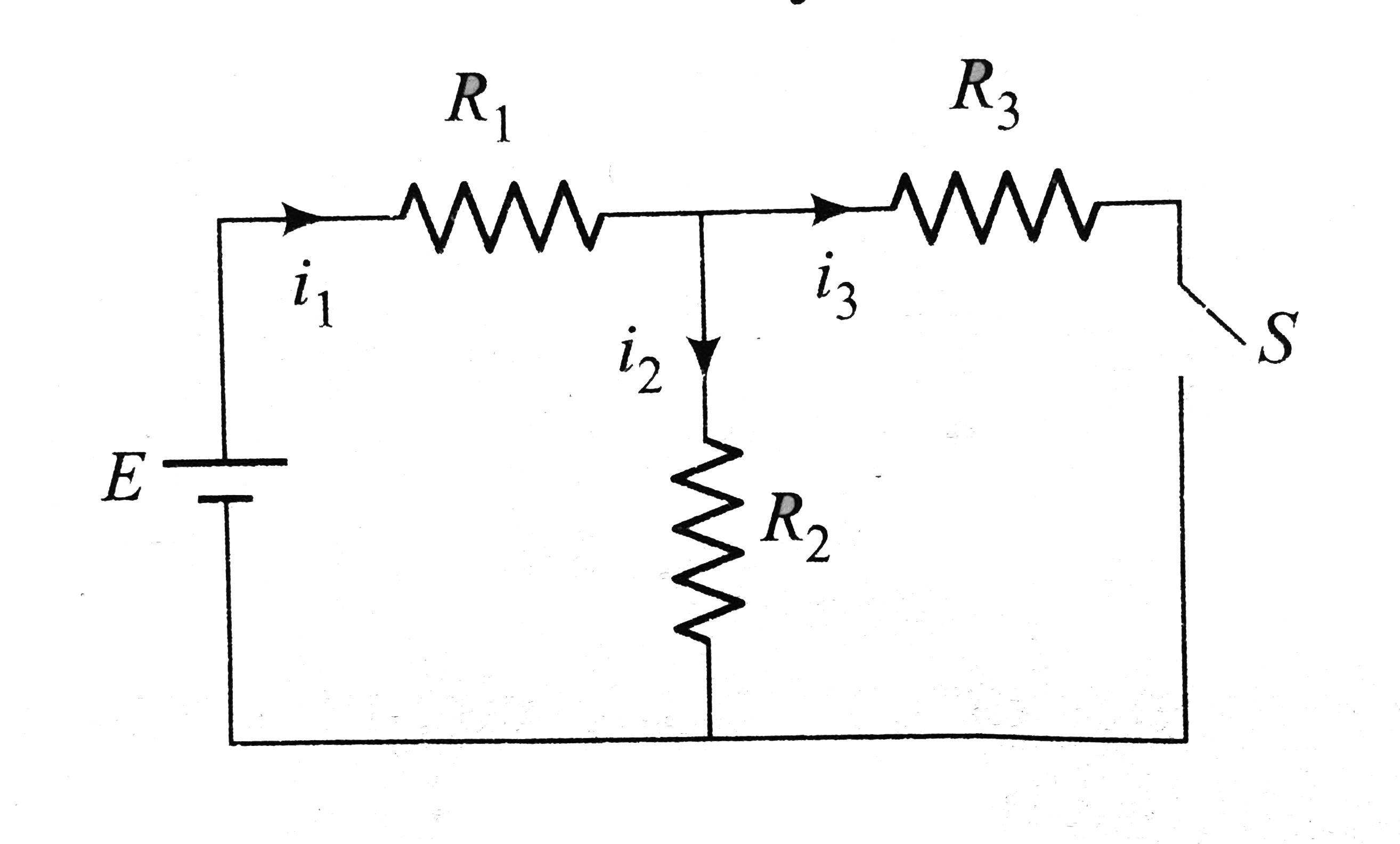
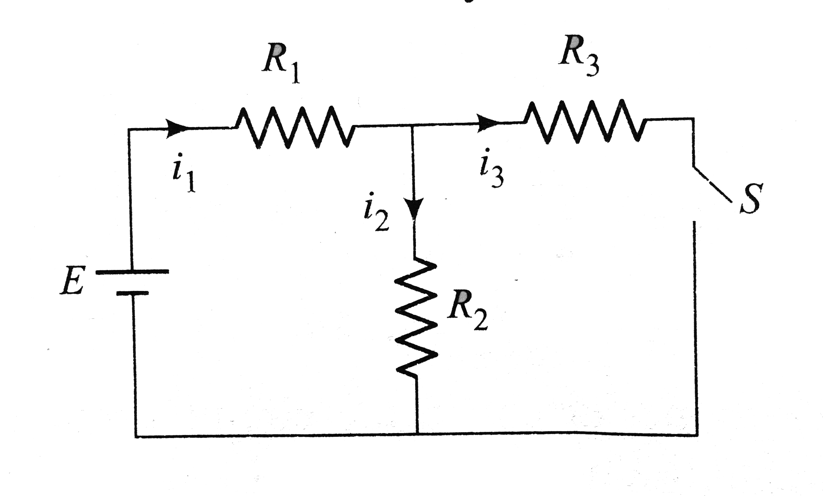
In the circuit shown in adjoining fig E =10V, R1=1ΩR2=2Ω,R3=3ΩandL=2H. Calculate the value of current i1,i2andi3 immidiately after key S is closed :-
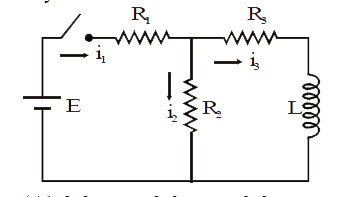
3.3 amp, 3.3 amp, 3.3 amp
3.3 amp, 3.3 amp, 0 amp
3.3 amp, 0 amp, 0 amp
3.3 amp , 3.3 amp 1.1 amp
The correct Answer is:B
Step by step video, text & image solution for In the circuit shown in adjoining fig E =10V, R_(1)=1 Omega R_(2)=2 Omega, R_(3)=3 Omega and L=2H. Calculate the value of current i_(1), i_(2) and i_(3) immidiately after key S is closed :- by Physics experts to help you in doubts & scoring excellent marks in Class 12 exams.
Topper's Solved these Questions
- BOOK - MOTIONCHAPTER - ELECTRO MAGNETIC INDUCTIONEXERCISE - EXERCISE-172videos
ELECTRO MAGNETIC INDUCTION
- BOOK - MOTIONCHAPTER - ELECTRO MAGNETIC INDUCTIONEXERCISE - EXERCISE-2 (Objective problems (Analytical questions))70videos
ELECTRO MAGNETIC INDUCTION
- BOOK - MOTIONCHAPTER - ELECTRO MAGNETIC INDUCTIONEXERCISE - QUESTIONS FOR PRACTICE (Type- IV: Questions based on induced Parameters :-)10videos
ELECTRO MAGNETIC INDUCTION
- BOOK - MOTIONCHAPTER - Electrical Instrument EXERCISE - EXERCISE -316videos
Electrical Instrument
- BOOK - MOTIONCHAPTER - ELECTRO MAGNETIC WAVES EXERCISE - EXERCISE - 3 (SECTION - B)8videos
ELECTRO MAGNETIC WAVES
Similar Questions
In the circuits show ε=15V,R1=1Ω,R2=1Ω,R3=2ΩandL=15H . Find the current i1,i2,i3 (i) immediately after the switch is closed (ii) immediately after the opening from the closed position (iii) sufficiently long after , the switch is opened f rom the colsed position,
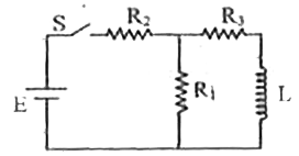
View SolutionFor the circuit shown E=50 V R1=10Ω,R2=20Ω,R3=30Ω L = 2.0 mH . The current through R1 and R2 are ________ . And _______ immediate after the switch is closed.
 View Solution
Knowledge Check
- Question 1 - Select One
In the circuit shown below E1=4.0V,R1=2Ω,E2=6.0V,R2=4Ω and R3=2Ω. The current I1 is
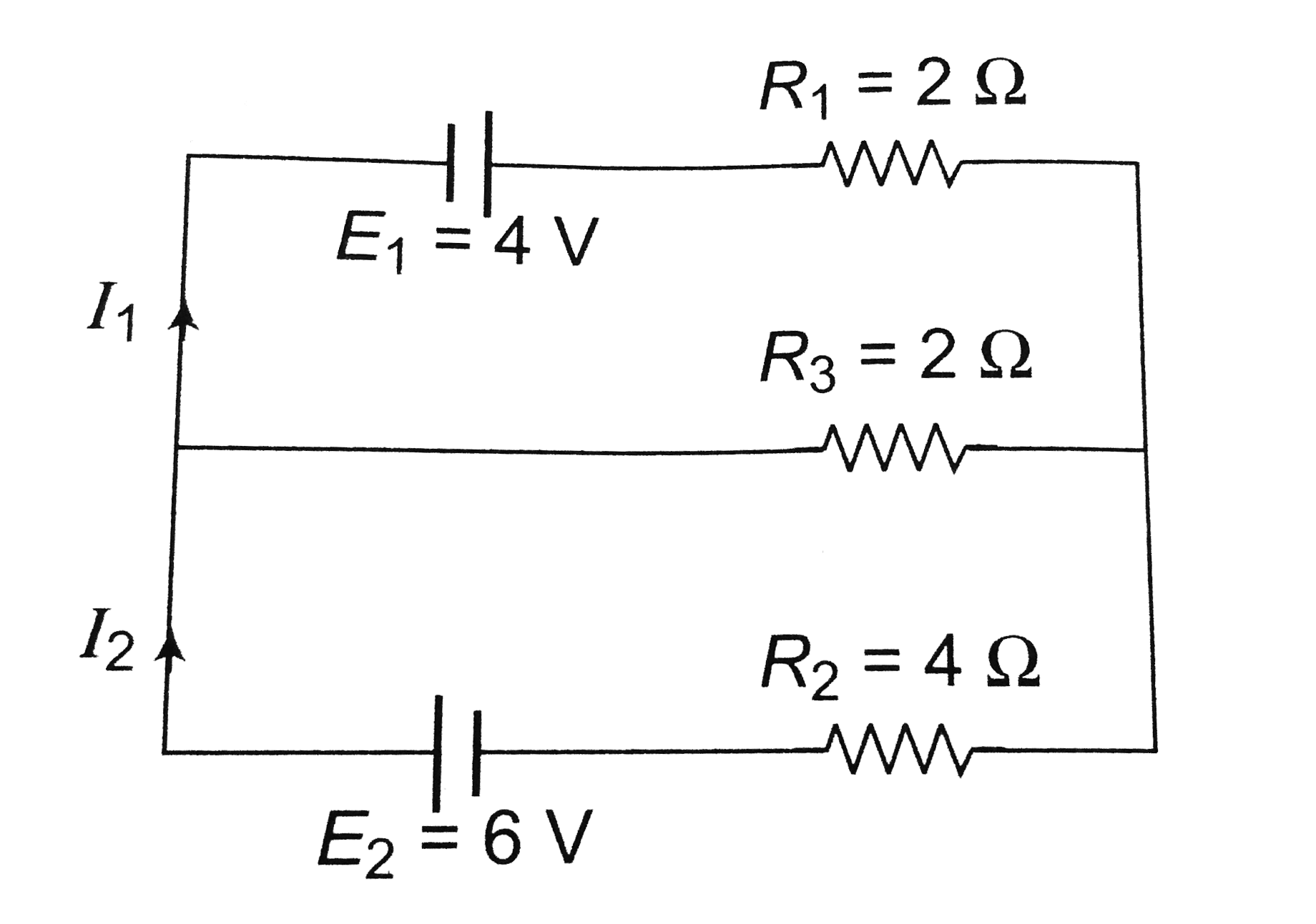 A1.6AB1.8AC1.25AD1.0A
 - Question 2 - Select One
In the circuit shows in Fig E=15V, R1=1Ω, R2=1Ω, R3=2Ω, and L=1.5H. The currents flowing through R1,R2,and R3 are i1,i2, and i3, respectively.
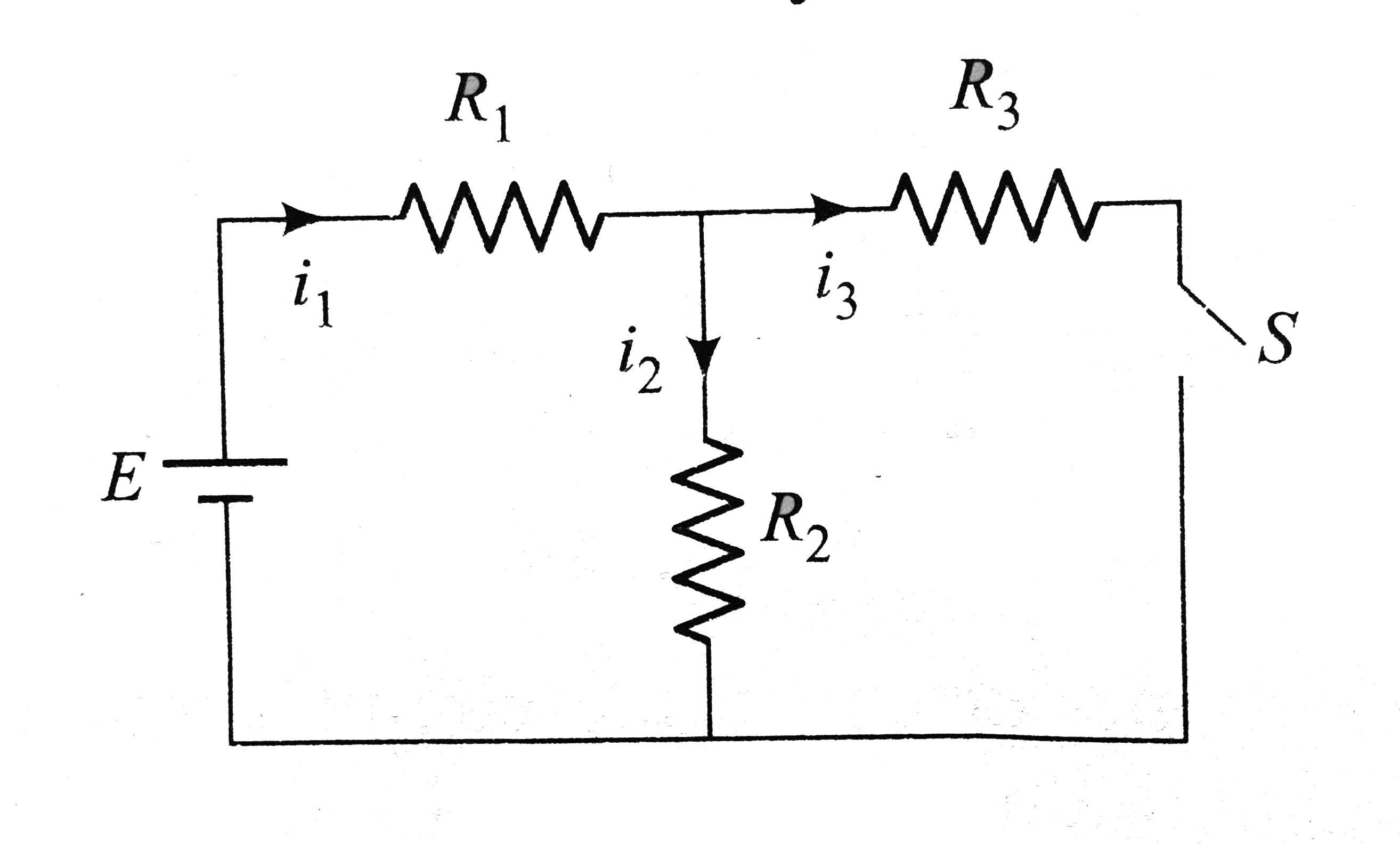
After the circuit reaches the steady state,Ai1=9A, i2=6A, i3=3ABi1=9A, i2=3A, i3=6ACi1=6A, i2=6A, i3=0ADi1=0A, i2=0A, i3=0A - Question 3 - Select One
In the circuit shows in Fig E=15V, R1=1Ω, R2=1Ω, R3=2Ω, and L=1.5H. The currents flowing through R1,R2,and R3 are i1,i2, and i3, respectively.
Immediately after tuning switch S on,Ai1=i2=7.5A, i3=0ABi1=i3=5A, i2=0ACi1=i2=9A, i3=0ADi1=i2=i3=0A
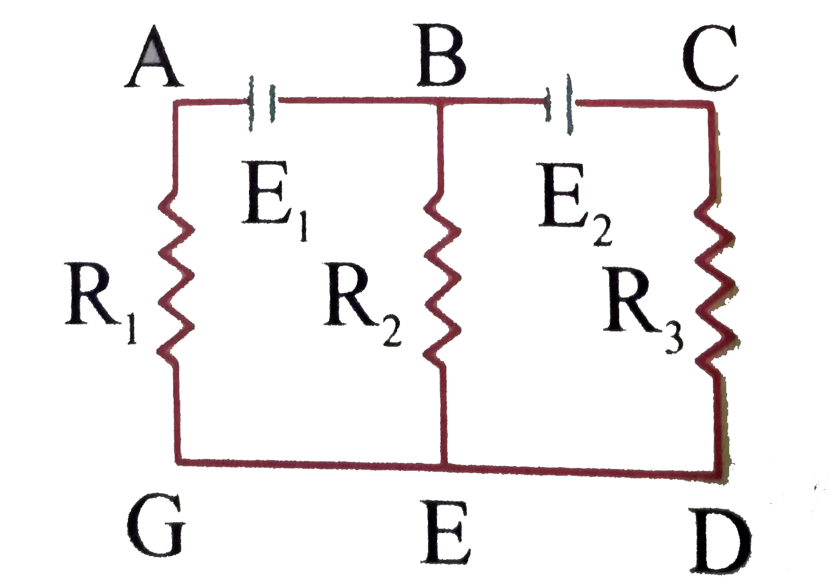
In the given circuit values are as follows
ε=2V,ε2=4V,R1=1Ω and R2=R3=1Ω.
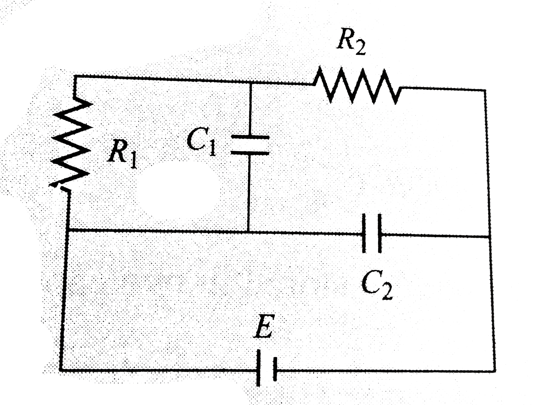
Calculate the current through R1,R2 and R3View SolutionIn the circuit shown in fig. R1=10Ω,R2=Ω,C1=1μF,C2=2μF, and E =6V. Calculate the charge on each capactor in the stedy state.
 View Solution
In the circuit shown in figure, R(1)=1Ω,R2=2Ω,C1=1μF,C2=2μF and E=6V. Calculate charge on each capacitor in steady state
 View Solution
In the circuit shows in Fig E=15V, R1=1Ω, R2=1Ω, R3=2Ω, and L=1.5H. The currents flowing through R1,R2,and R3 are i1,i2, and i3, respectively.
Immediately after connecting switch S,View SolutionIn the circuit shown in figure
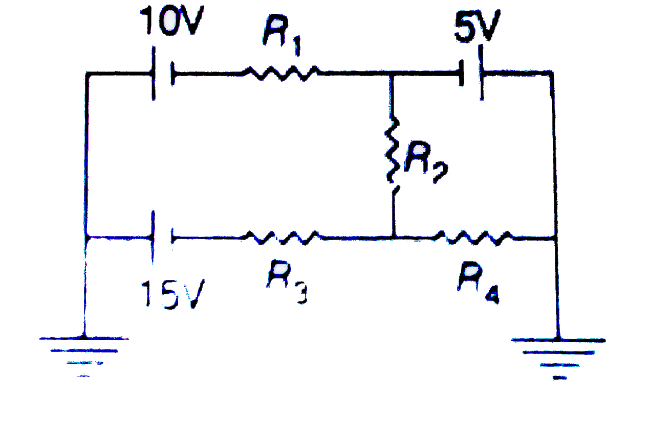
Current through R2 is zero if R4=2Ω and R3=4Ω In this caseView Solution

