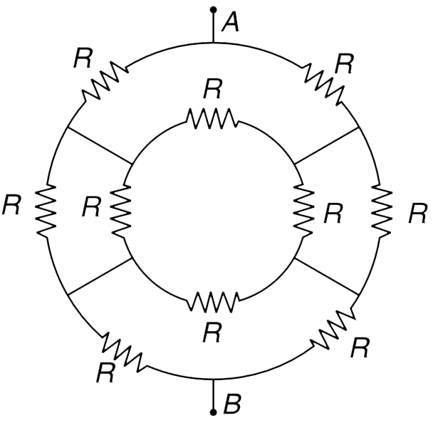
For the circuit shown in figure given below, the equivalent resistance points A and B is
10Ω
5Ω
103Ω
2Ω
The correct Answer is:C
Step by step video, text & image solution for For the circuit shown in figure given below, the equivalent resistance points A and B is by Physics experts to help you in doubts & scoring excellent marks in Class 12 exams.
Updated on:21/07/2023Topper's Solved these Questions
- CURRENT ELECTRICITYBook:DC PANDEYChapter:CURRENT ELECTRICITYExercise:Match the columns
Explore 4 Videos
- COMMUNICATION SYSTEMBook:DC PANDEYChapter:COMMUNICATION SYSTEMExercise:Subjective
Explore 11 Videos
- ELECTROMAGNETIC INDUCTIONBook:DC PANDEYChapter:ELECTROMAGNETIC INDUCTIONExercise:Medical entrances gallery
Explore 25 Videos
Similar Questions
Knowledge Check
Each resistance of the circuit shown in figure is r. The equivalent resistance between A and B is
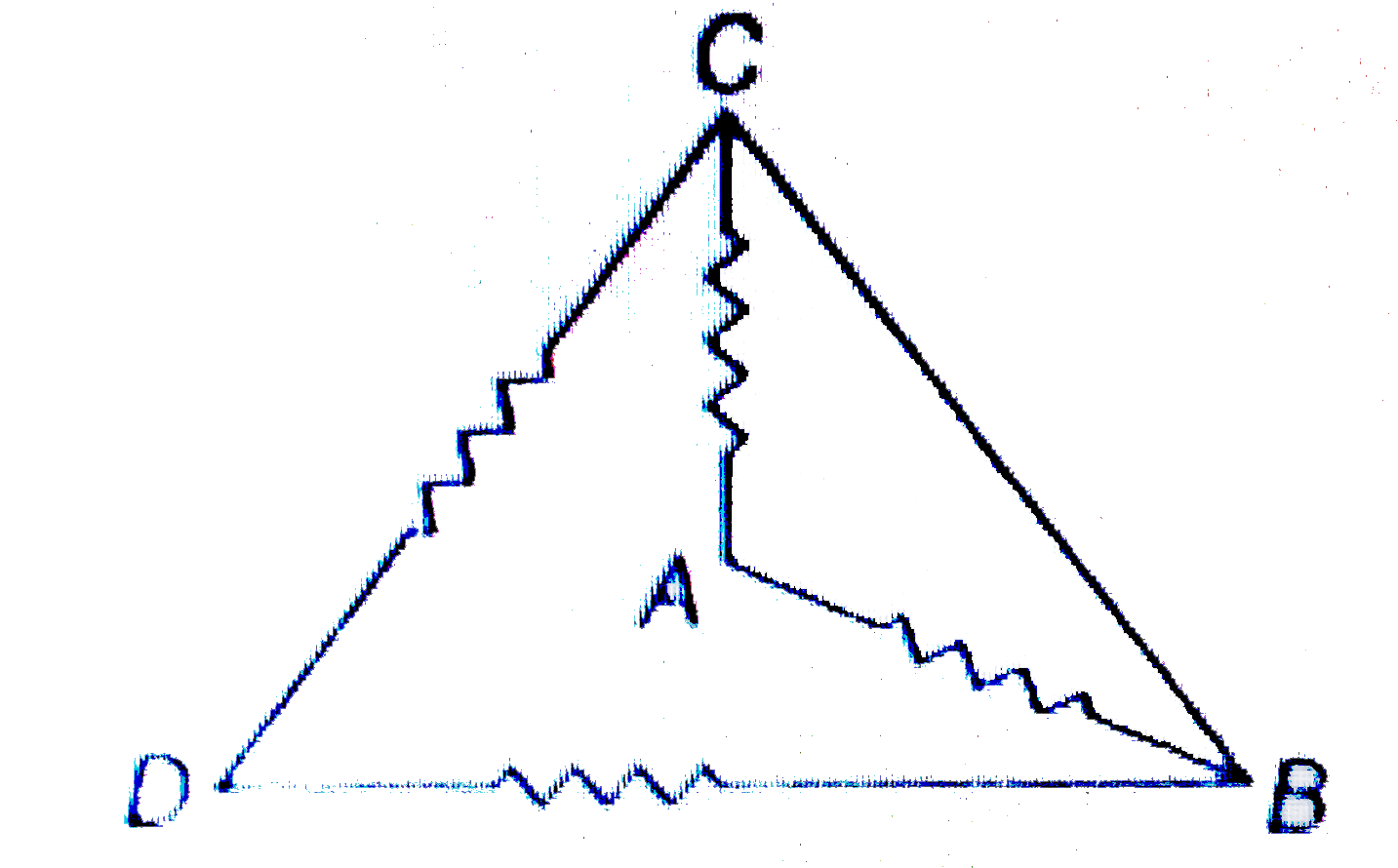 ArBr/4Cr/2D5r/8
Consider the circuit as shown in figure. The equivalent resistance between A and B is
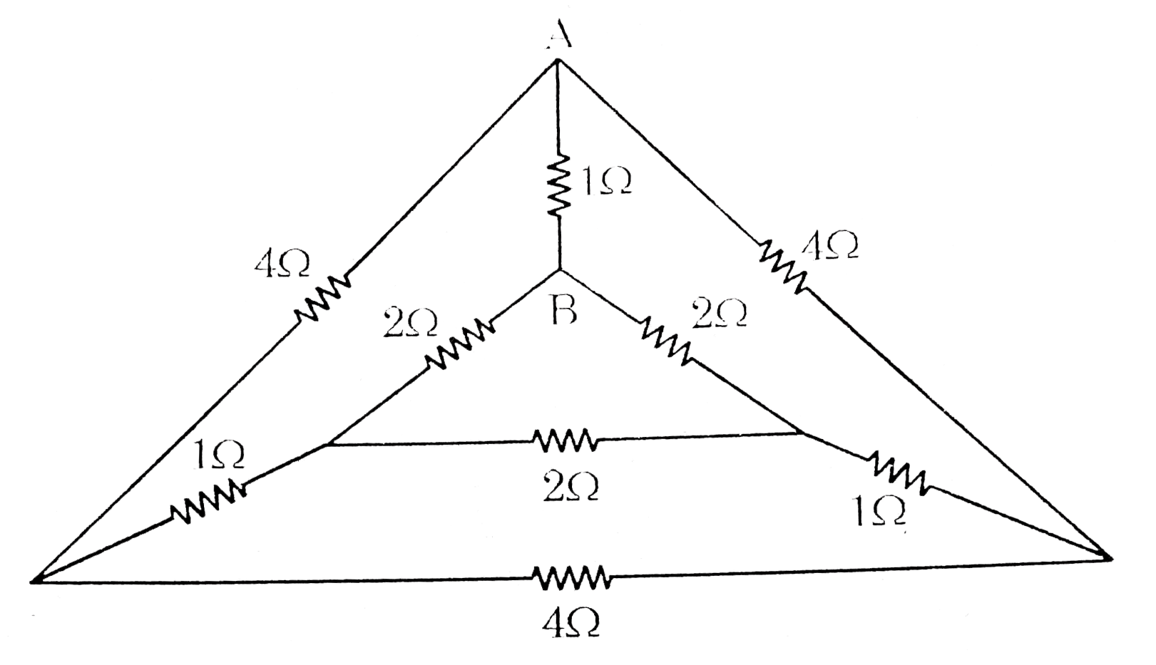 A97ΩB19ΩC79ΩDNone
In the given figure, the equivalent resistance between the points A and B is
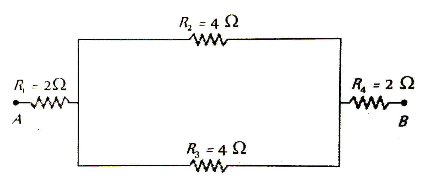 A8ΩB6ΩC4ΩD2Ω
In the circuit arragement shown in the figure , the equivalent resistance between points A and B :
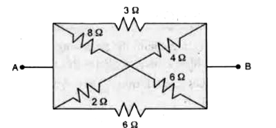
View SolutionIn the circuit shown in figure R=55Ω the equivalent resistance between the point P and Q is
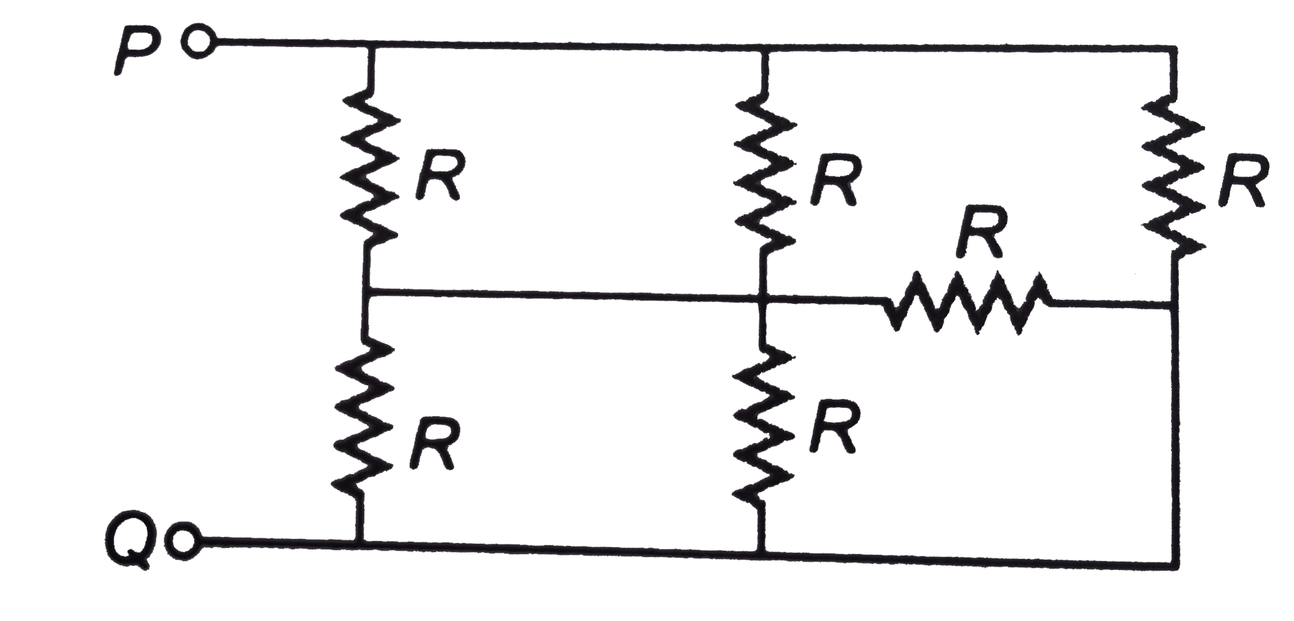
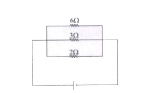
View SolutionIn the circuit shown below, what is the equivalent resistance ?
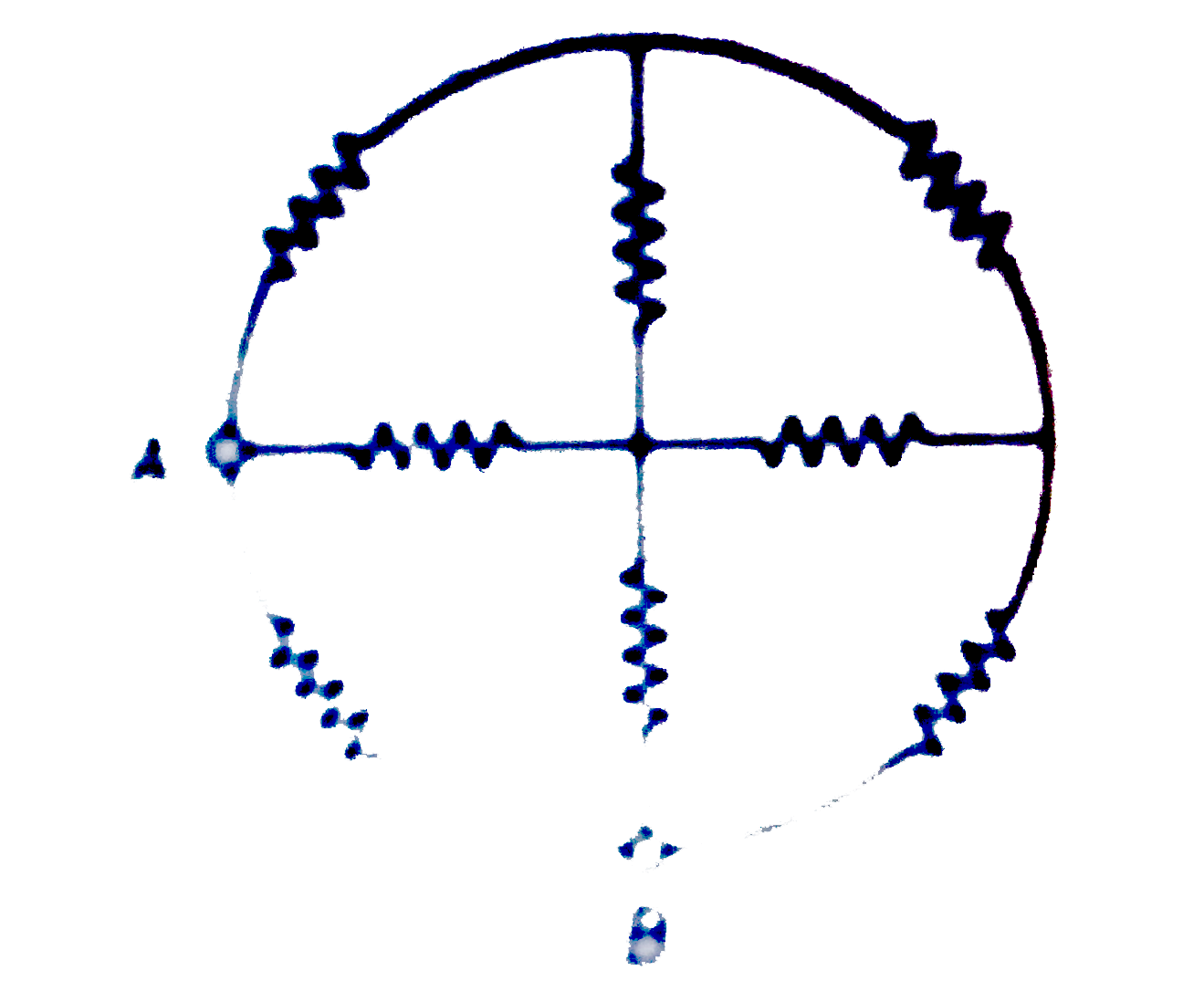
View SolutionEight resistances each of resistance 5Ω are connected in the circuit as shown in figure. The equivalent resistance between A and B is
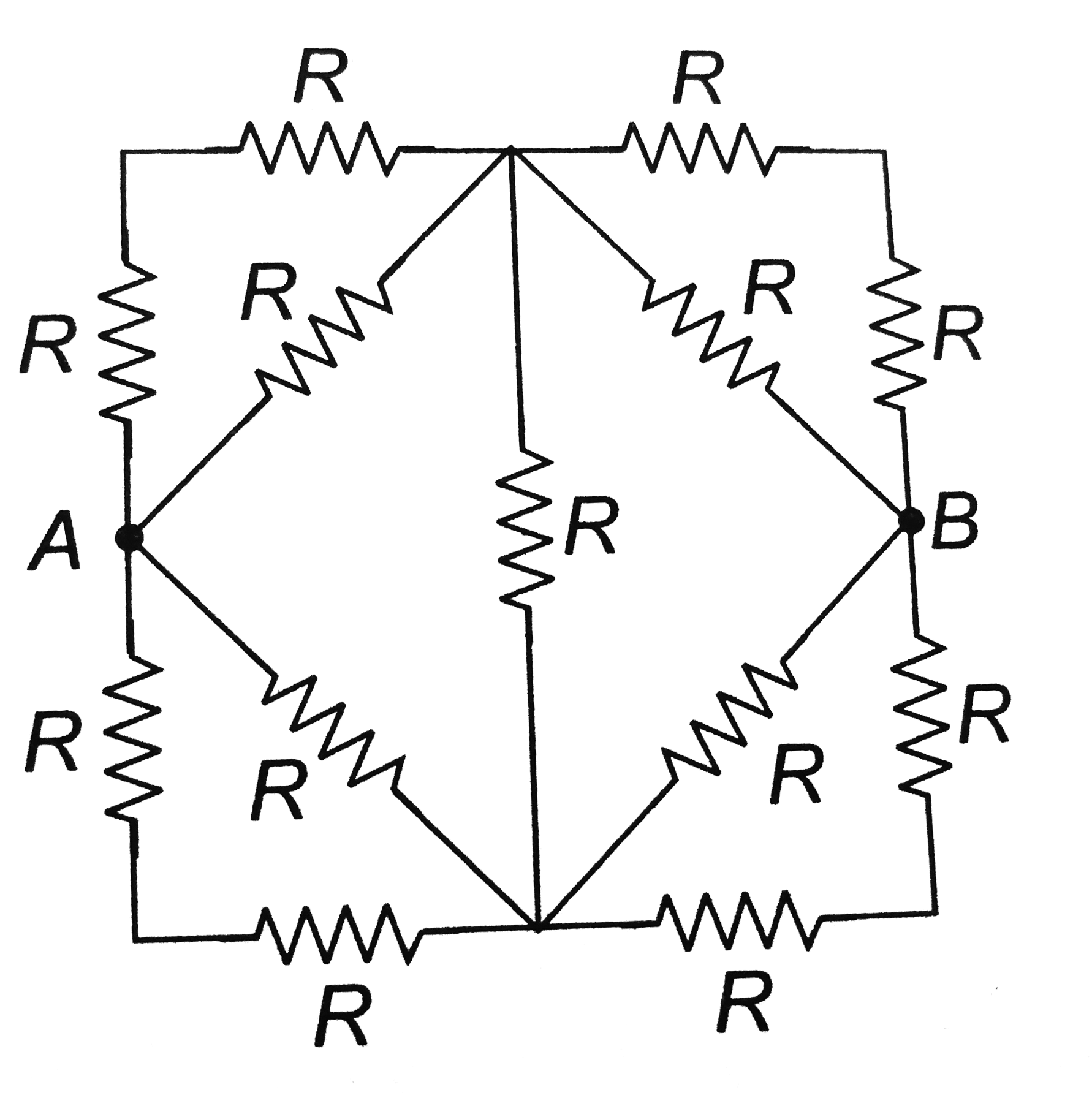
View SolutionThirteen resistances each of resistance R ohm are connected in the circuit as shown in the figure below. The effecitve resistance between A and B is
View Solution


