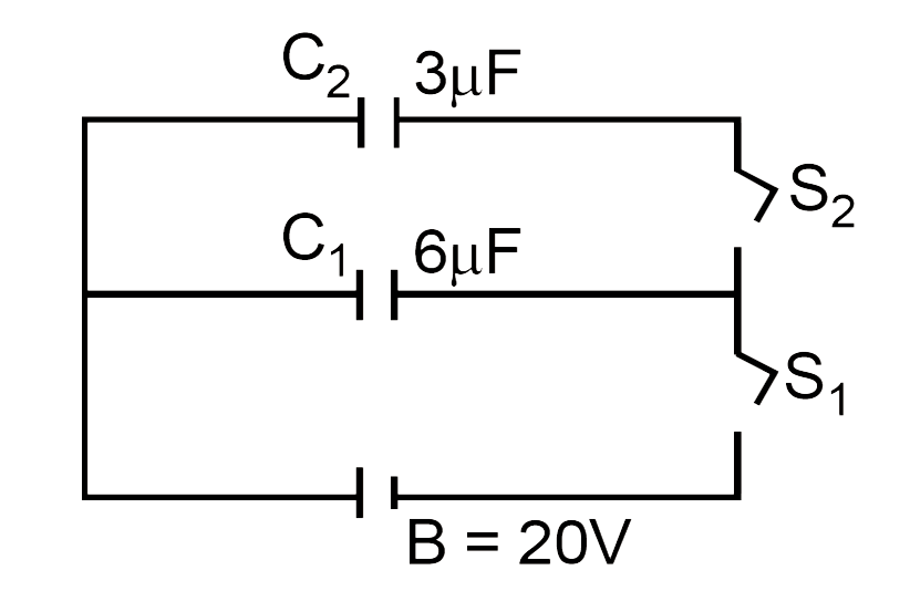
In the circuit shown here C1=6μF,C2=3μF and battery B=20V. The Switch S1 is first closed. It is then opened and afterwards S2 is closed. What is the charge finally on C2
120μC
80μC
40μC
20μC
The correct Answer is:C
Step by step video, text & image solution for In the circuit shown here C_(1) = 6muF, C2 = 3muF and battery B = 20V. The Switch S_(1) is first closed. It is then opened and afterwards S_(2) is closed. What is the charge finally on C_(2) by Physics experts to help you in doubts & scoring excellent marks in Class 12 exams.
Updated on:21/07/2023Topper's Solved these Questions
- ELECTROSTATIC POTENTIAL AND CAPACITORSBOOK - DC PANDEYCHAPTER - ELECTROSTATIC POTENTIAL AND CAPACITORSEXERCISE - (B) Chapter exercises
20 Videos
- ELECTROSTATIC POTENTIAL AND CAPACITORSBOOK - DC PANDEYCHAPTER - ELECTROSTATIC POTENTIAL AND CAPACITORSEXERCISE - (C) Chapter exercises
50 Videos
- ELECTROSTATIC POTENTIAL AND CAPACITORSBOOK - DC PANDEYCHAPTER - ELECTROSTATIC POTENTIAL AND CAPACITORSEXERCISE - Check point 2.5
20 Videos
- ELECTROMAGNETIC WAVESBOOK - DC PANDEYCHAPTER - ELECTROMAGNETIC WAVESEXERCISE - Sec C
22 Videos
- ELECTROSTATICSBOOK - DC PANDEYCHAPTER - ELECTROSTATICSEXERCISE - Medical entrances gallery
37 Videos
Similar Questions
In the circuit shown below, C1=6μF,C2=3μF and battery. E=20V. The switch S{1} is first closed. It is then opened and. afterwards S2 is closed. What is the charge (in μC)onC_{2} ?
'(##CEN_KSR_PHY_JEE_CO19_E01_014_Q07##)'
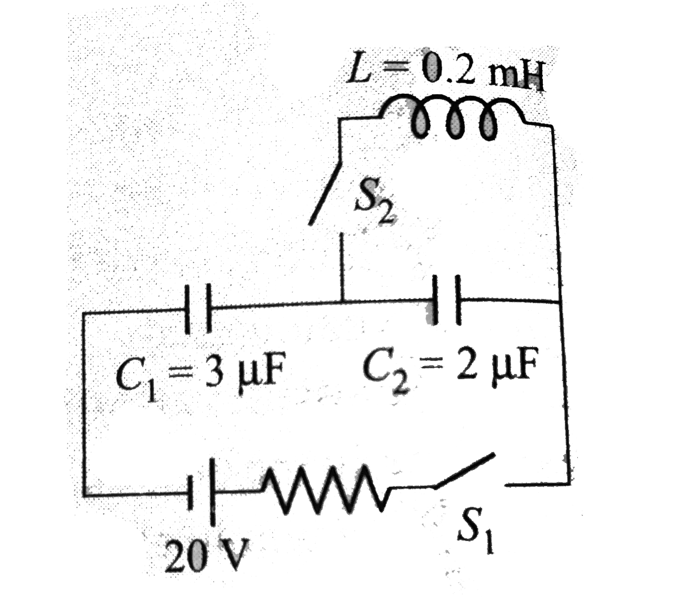
View SolutionThe circuit shows in Fig. is in the steady state with switch S1 closed. At t=0,S1 is opened and switch S2 is closed.
a. Derive expression for the charge on capacitor C2 as a function of time.
b. Determine the first instant t, when the energy in the inductor becomes one-third of that in the capacitor.
View Solution
Knowledge Check
In the circuit shown in, C1=6μF,C2=3μF, and battery B=20V. The switch S1 is first closed. It is then opened, and S2 is closed. What is the final charge on C2
 . A120μCB80μCC40μCD20μC
Consider the circuit shown where C1=6μF,C2=3μF and V=20V. Capacitor C1 is first charged by closing the switch S1. Switch S1 is then opened, and the charged capacitor is connected to the uncharged capacitor C2 by closing S2.
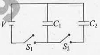 ATotal charge that has flown through the battery is 120μC.BFinal charge on C1 after opening switch S1 and closing switch S2is80μC.CFinal charge on C2 after opening switch S1 and closing switch S2is40μCDTotal heat produced after closing switch S2is1.8mJ.
In the circuit shown, battery, ammeter , and voltmeter are ideal and the switch S is initially closed as shown. When switch S is opened
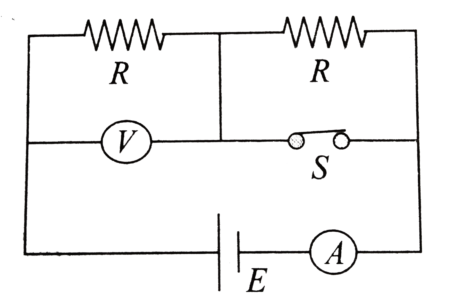 Aequivalent resistance across the battery increasesBpower dissipated by left resistance R increasesCvoltmeter reading decreasesDammeter reading decreases.
In the circuit shown the capacitors are C1=15μF,C2=10μFandC3=25μF. Find
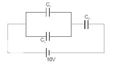
the charge on each capacitor and
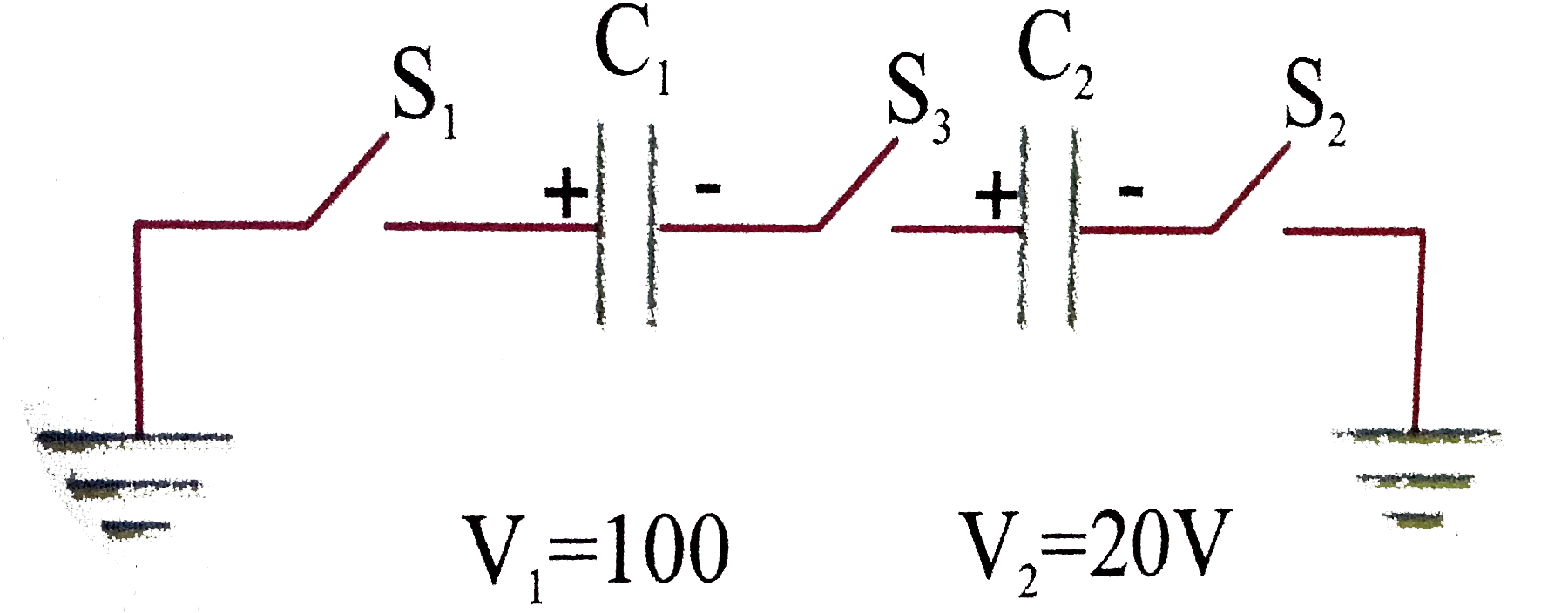
View SolutionIn the circuit shown in figure C1=1μF and C2=2μF. The capacitor C1 is charged to 100V and the capacitor C2 is charged to 20V. After charging then are connected as shown. When the switches S1,S2 and S3 are closed, the charged flowing through S1 is
 .
.
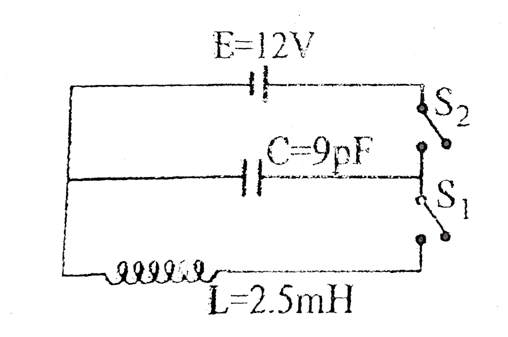
View SolutionIn the circuit shown, the capacitor is initially charged with a 12V battery, when switch S1 is open and switch S2 is closed. S1 is then closed and, at the same time, S2 is opened. The maximum value of current in the circuit is
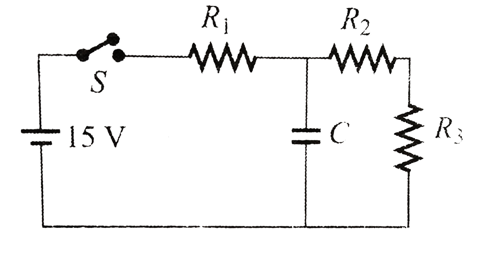
View SolutionFigure shows a battery with emf 15 V in a circuit with R1=30Ω,R2=10Ω,R3=20Ω and capacitance C=10μF. The switch S is initially in the open position and is then closed at time t= 0. What will be the fimal steady - state charge on capacitor?
View SolutionIn the circuit shown in figure C1=2C2. Capacitance C1 is charged to a potential of V. The current in the circuit just after the switch S is closed is

View Solution
