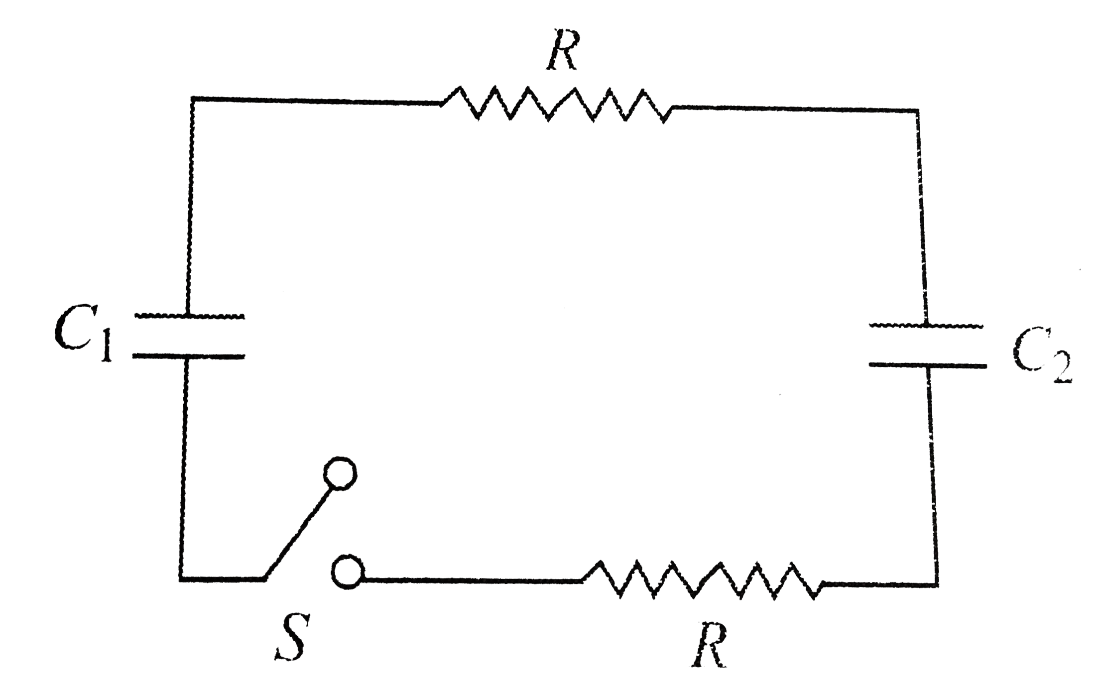
In the circuit shown in figure C1=2C2. Capacitance C1 is charged to a potential of V. The current in the circuit just after the switch S is closed is

zero
2VR
infinite
V2R
The correct Answer is:D
Step by step video, text & image solution for In the circuit shown in figure C_(1) = 2 C_(2). Capacitance C_(1) is charged to a potential of V. The current in the circuit just after the switch S is closed is by Physics experts to help you in doubts & scoring excellent marks in Class 11 exams.
Updated on:21/07/2023Topper's Solved these Questions
- ELECTROSTATICSBOOK - DC PANDEYCHAPTER - ELECTROSTATICSEXERCISE - JEE Advanced
44 Videos
- ELECTROSTATICSBOOK - DC PANDEYCHAPTER - ELECTROSTATICSEXERCISE - Comprehension
36 Videos
- ELASTICITYBOOK - DC PANDEYCHAPTER - ELASTICITYEXERCISE - Medical entrances s gallery
21 Videos
- EXPERIMENTSBOOK - DC PANDEYCHAPTER - EXPERIMENTSEXERCISE - Subjective
15 Videos
Similar Questions
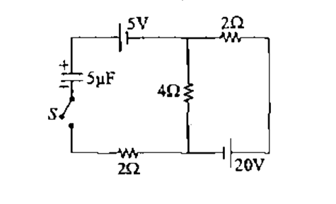
In the circuit shown in figure 3.242 capacitor is charged with 50μC charge. Find the current in 4Ω resistance just after switch S is closed.
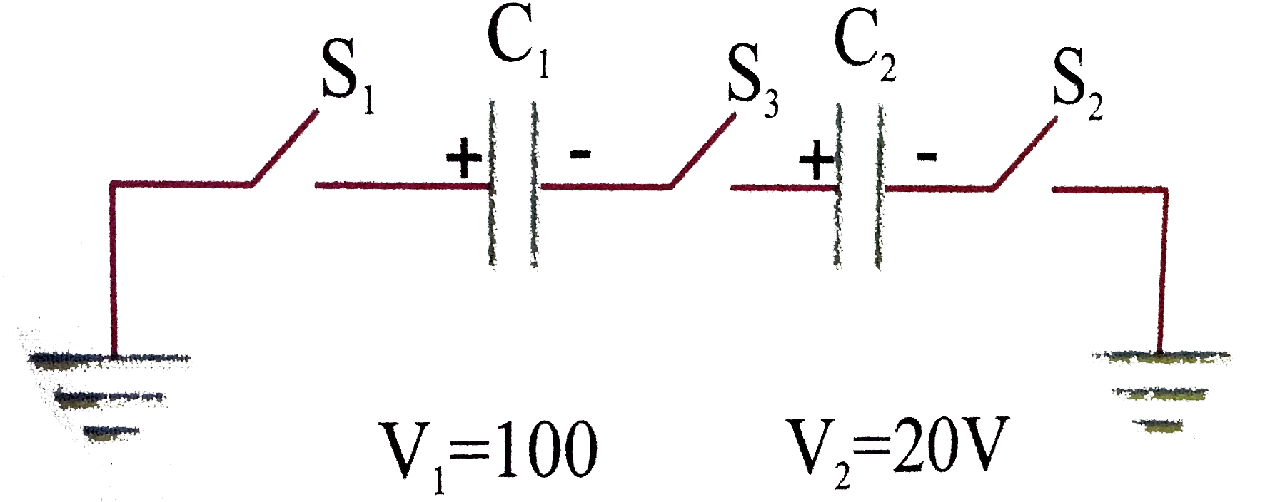
View SolutionIn the circuit shown in figure C1=1μF and C2=2μF. The capacitor C1 is charged to 100V and the capacitor C2 is charged to 20V. After charging then are connected as shown. When the switches S1,S2 and S3 are closed, the charged flowing through S1 is
 .
.
View Solution
Knowledge Check
In the circuit shown in fig. C1=2C2 Initially, capacitor C1 is charged to a potential of V. The current in the circuit just after the switch S is closed is
 A0B2V/RC∞DV/2R
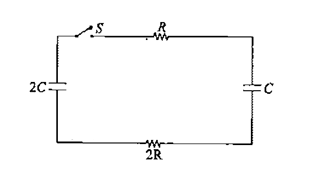
In the circuit shown in figure-3.345 the capacitor of capacitance C is charged to a potential difference V. The current in the circuit just after the closing of switch S is :
 AV3RB3VRCV2RDzero
n the circuit shown in the figure, the capacitor C is charged to a potential Vo The heat generated and charge flow, in the circuit to when the switch S is closed, is
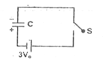 A△q=2CVoB△H=4CVoC△q=4CVoD△H=8CVo
In the circuit shown in figure-3.351 the capacitors are initially uncharged. The current through resistor PQ just after closing the switch is :
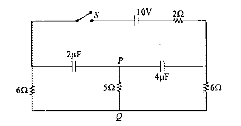
View SolutionIn the circuit shown in the figure, the capacitor C is charged to a potential Vo. The heat generated in the circuit when the switch S is closed, is
View SolutionIn the circuit shown in figure C1=C2=2μF. Then charge stored in
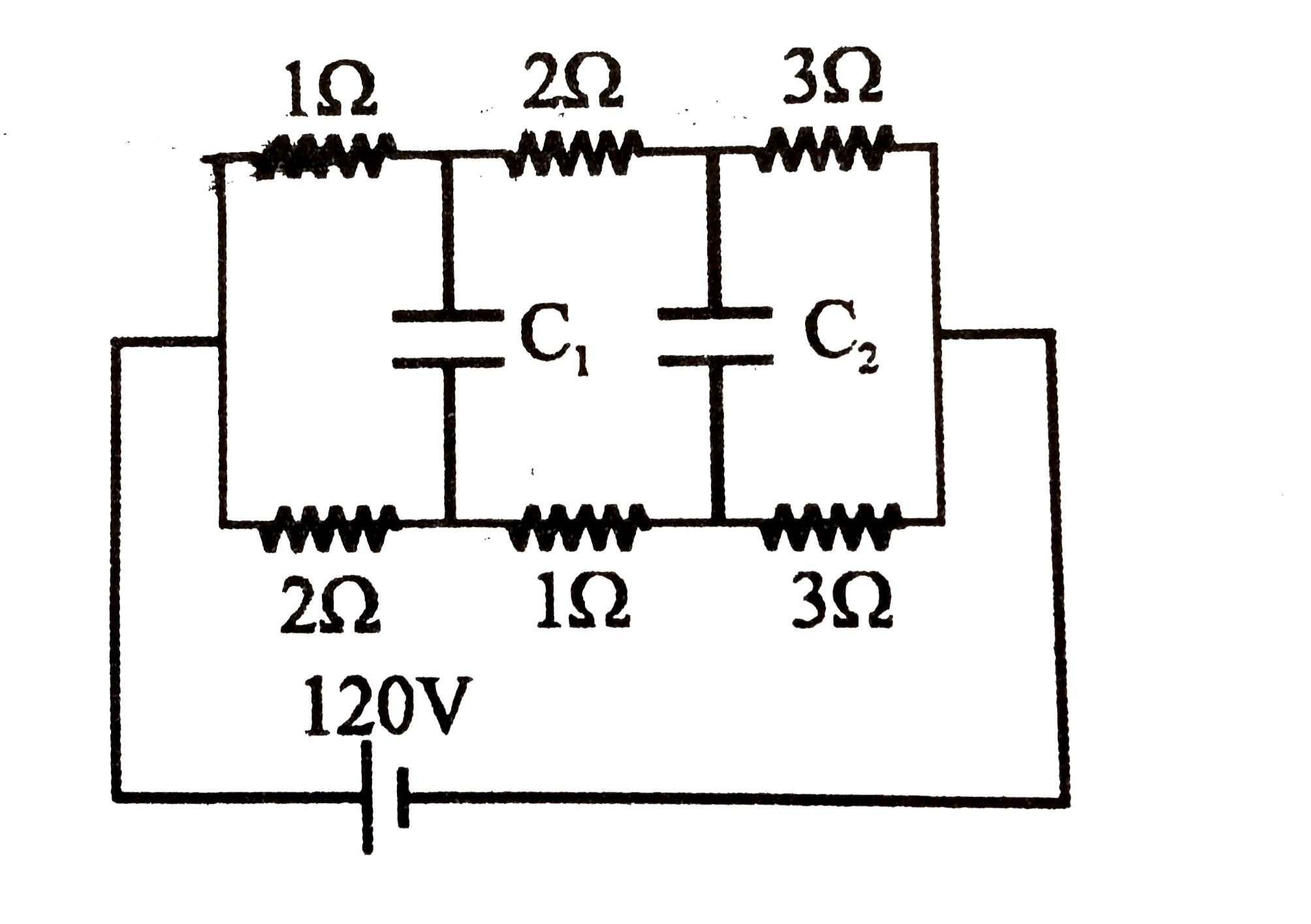
View SolutionIn which of the following circuits is the current maximum just after the switch S is closed?

View SolutionThe circuit consists of two resistors (of resistance R1=20Ω and R2=10Ω), a capacitor (of capacitance C=10μF) and two ideal cells. In the circuit shown the capacitor is in steady state and the switch S is open
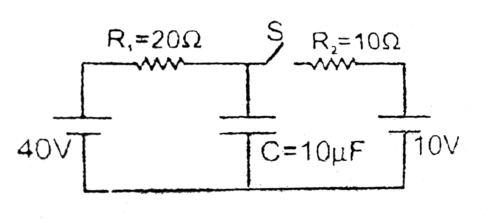
The current through the resistor R2 just after the switch S is closed is :
View Solution
