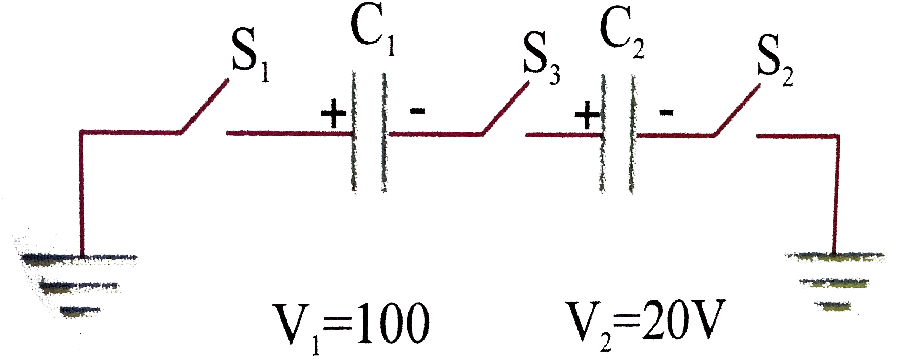
In the circuit shown in figure C1=1μF and C2=2μF. The capacitor C1 is charged to 100V and the capacitor C2 is charged to 20V. After charging then are connected as shown. When the switches S1,S2 and S3 are closed, the charged flowing through S1 is
 .
.
When S1,S2 and S3 are closed, both the capacitors are in parallel with unlike charged plates together. So, they attain a common potential.
Before closing the switches,
Charge on C1 is q1=100×1=100μC
Charge on C2 is q2=20×2=40μC
After closing the switches
Common potential V=q1−q2C1+C2=100−403=20V
Now final charges q11=C1V=1×20=20μC
q12=C2V=2×20=40μC
The charge that flows through S1 is
Δq=100−20=80μC.
Topper's Solved these Questions
- CAPACITANCEBook:NARAYNAChapter:CAPACITANCEExercise:C.U.Q
Explore 54 Videos
- CAPACITANCEBook:NARAYNAChapter:CAPACITANCEExercise:Assertion & Reasoning
Explore 16 Videos
- ATOMS Book:NARAYNAChapter:ATOMS Exercise:EXERCISE -4
Explore 47 Videos
- COMMUNICATION SYSTEMBook:NARAYNAChapter:COMMUNICATION SYSTEMExercise:Level-II(H.W)
Explore 25 Videos
Similar Questions
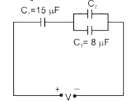
In the circuit shown in the figure, the total charge is 750μC and the voltage across capacitor C2 is 20 V. Then the charge on capacitor C2 is:
View SolutionTwo capacitors C1 and C2 are charged to same potential V, but with opposite polarity as shown in the figure. The switches S1 and S2 are then closed

View Solution
Knowledge Check
In the circuit shown, C1=C2=2μF. Capacitor C1 is charged to 50V and C1 is charge to 20V. After charging they are connected as shown. When S1,S2, and S3, are clsosed,
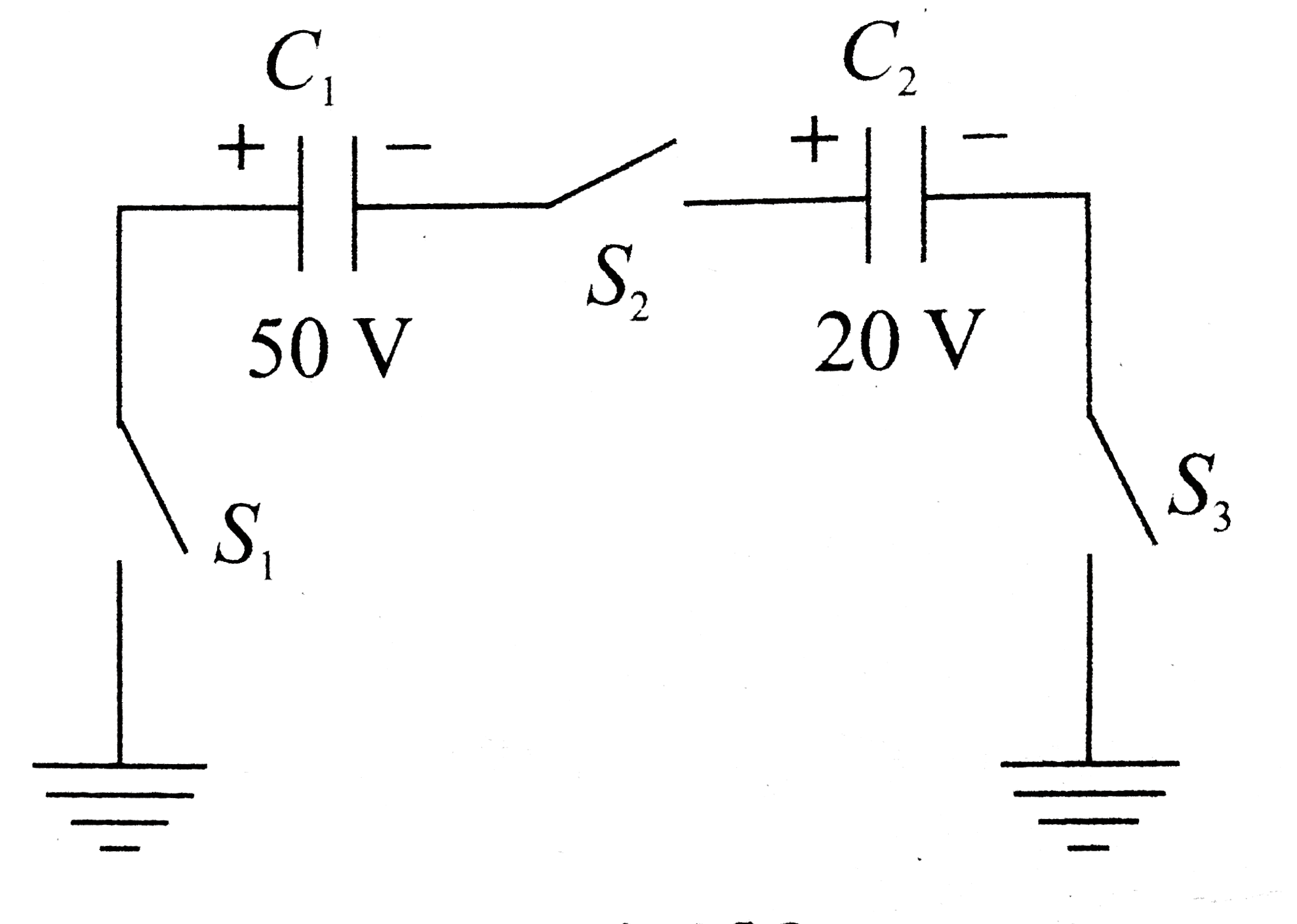 . A70μC of charge will pass through S1B100μC of chaarge will pass throuth S1C70μC of charge will pass throuth S3D40μC of chaarge will pass throuth S3.
In the circuit shown in the figure, if switches S1 and S2 have been closed for a long time, then charge on the capacitor.
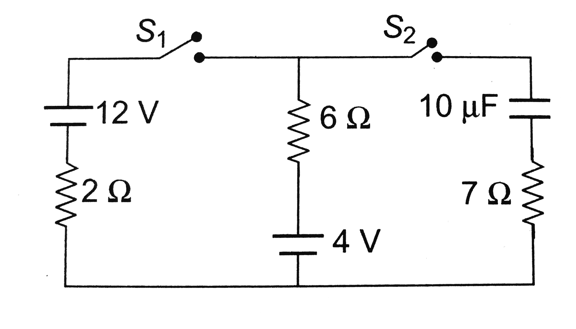 Ais 100μCBincreases to 200μC if one third of the gap of the capacitor's plates is filled with a dielectric (K=2) of same areaCboth (a) and (b) aboveDcharge on the capacitor remains unchanged if one third of the gap of the capacitor's plates is filled with a dielectric (K=2) of same area.
In the circuit shown in figure C1=2C2. Capacitance C1 is charged to a potential of V. The current in the circuit just after the switch S is closed is
 AzeroB2VRCinfiniteDV2R
Two capacitros of capacity 6μF are charged to 100 V and 50 V separately and connected as shown. Now all the three switches S1,S2 and S3 are closed.

Charges on both the capacitors in steady state will be (on 6μF first)
View SolutionTwo capacitors of capacity 6μF and 3μF are charge 100V and 50V separately and connected as shown in (Fig.4.201.) Now all the three switches S1,S2, and S3 are closed.
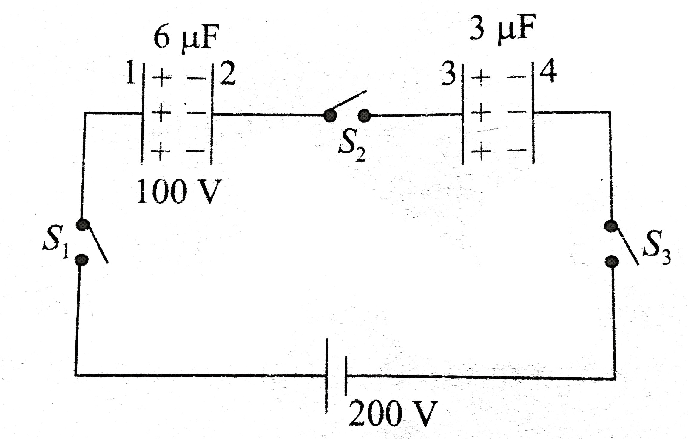
Charge on the 6μF capacitor in steady state will be.
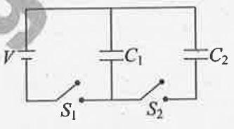
View SolutionConsider the circuit shown where C1=6μF,C2=3μF and V=20V. Capacitor C1 is first charged by closing the switch S1. Switch S1 is then opened, and the charged capacitor is connected to the uncharged capacitor C2 by closing S2.
View SolutionTwo capacitors of capacity 6μF and 3μF are charge 100V and 50V separately and connected as shown in Now all the three switches S1,S2, and S3 are closed.
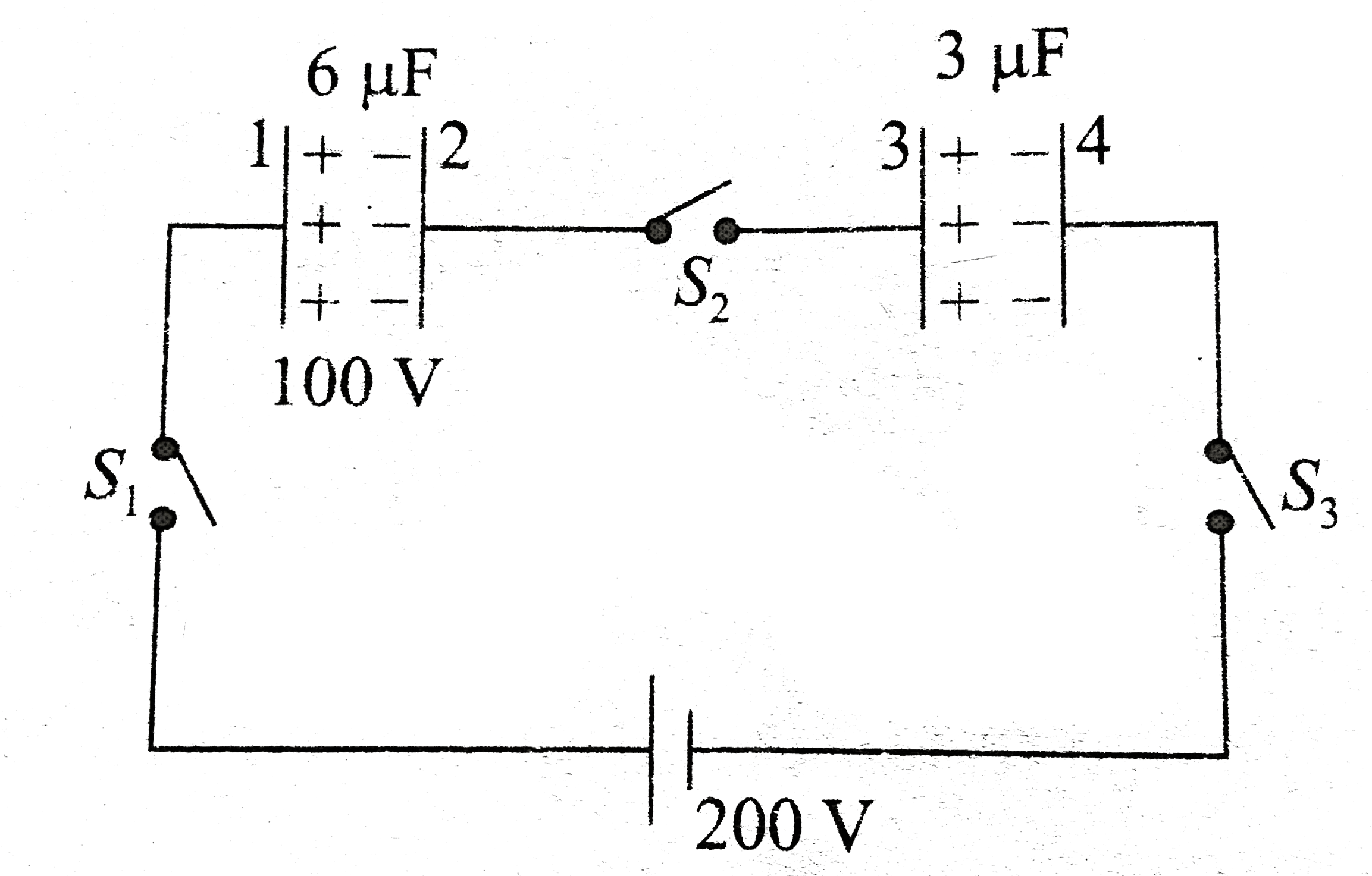
Charge on the 3μF capacitor in steady state willl be.
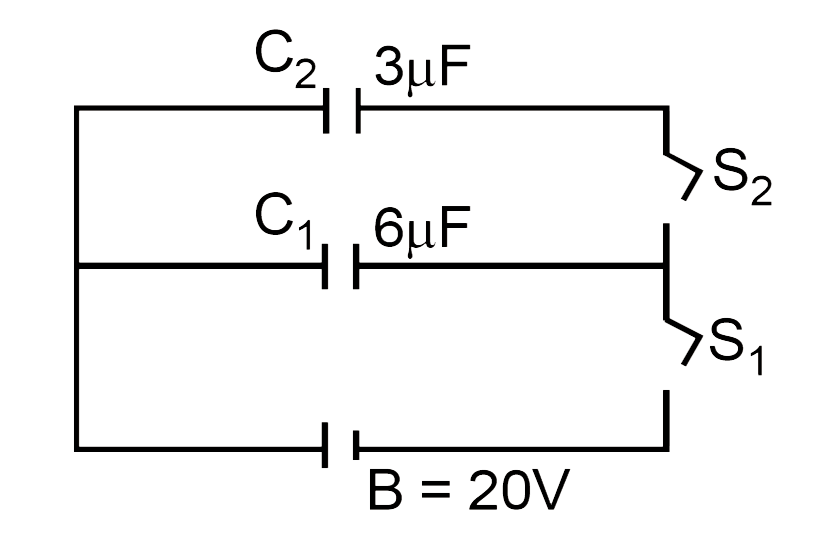
View SolutionIn the circuit shown here C1=6μF,C2=3μF and battery B=20V. The Switch S1 is first closed. It is then opened and afterwards S2 is closed. What is the charge finally on C2
View Solution

