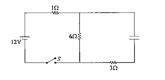
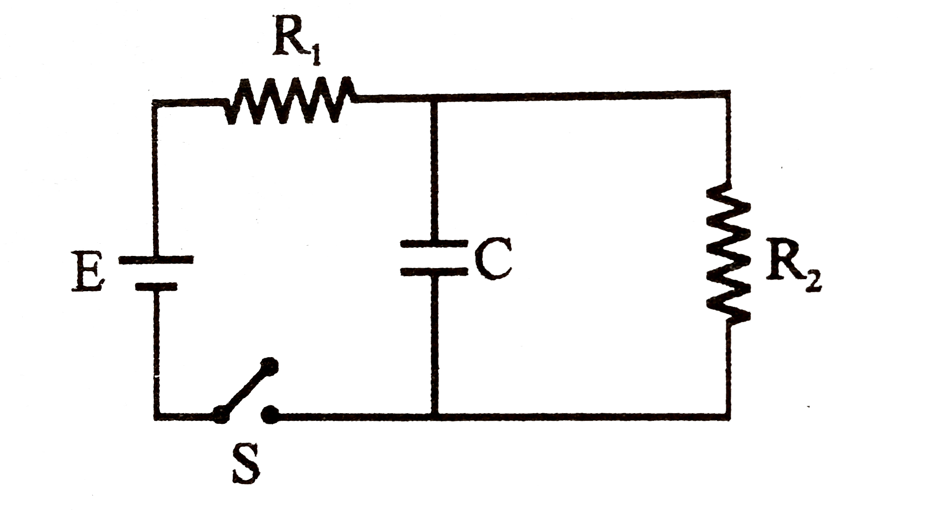
In the circuit shown in figure-3.348 when the switch is closed, the initial current through the 1Ω resistor just after closing the switch is
2A
4A
3A
6A
The correct Answer is:B,C,D
Step by step video, text & image solution for In the circuit shown in figure-3.348 when the switch is closed, the initial current through the 1 Omega resistor just after closing the switch is by Physics experts to help you in doubts & scoring excellent marks in Class 12 exams.
Updated on:21/07/2023Topper's Solved these Questions
Similar Questions
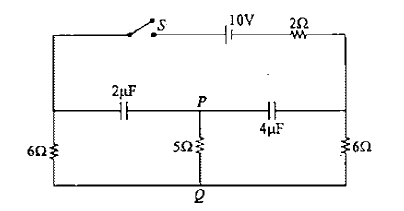
In the circuit shown in figure-3.351 the capacitors are initially uncharged. The current through resistor PQ just after closing the switch is :
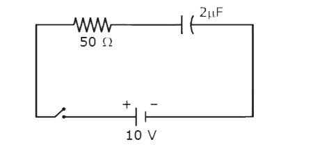
View SolutionFor the circuit shown in figure below, At t = 0, switch is closed, the initial current through resistor and final charge on capacitor are
View Solution
Knowledge Check
When the switch is closed, the initial current through the 1Ω resistor is
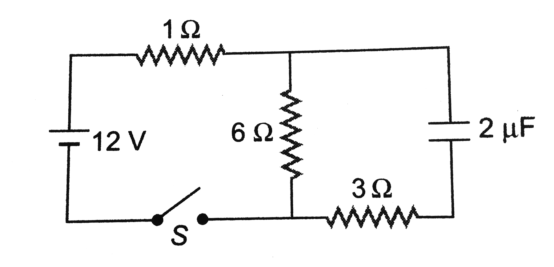 A2AB4AC3AD6
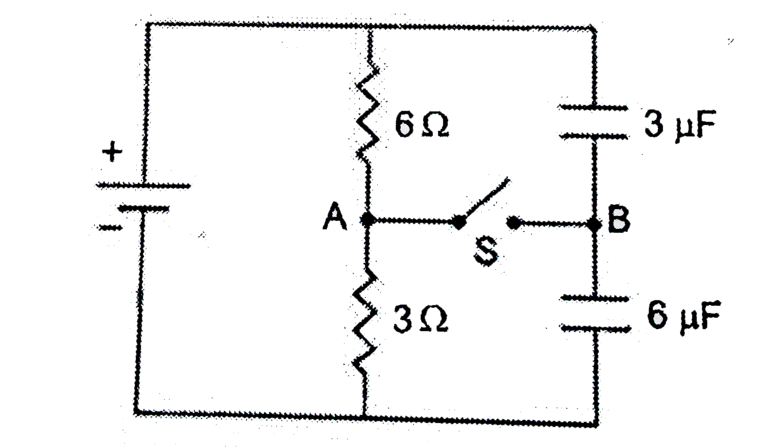
In the circuit shown above, when then switch S is closed,Ano charge flows through SBcharge flows from A to BCcharge flows from B to ADcharge flows initially from A to B and later from B to AIn the circuit shown in figure, the capacitors are initially uncharged. The current through resistor PQ just after closing the switch is
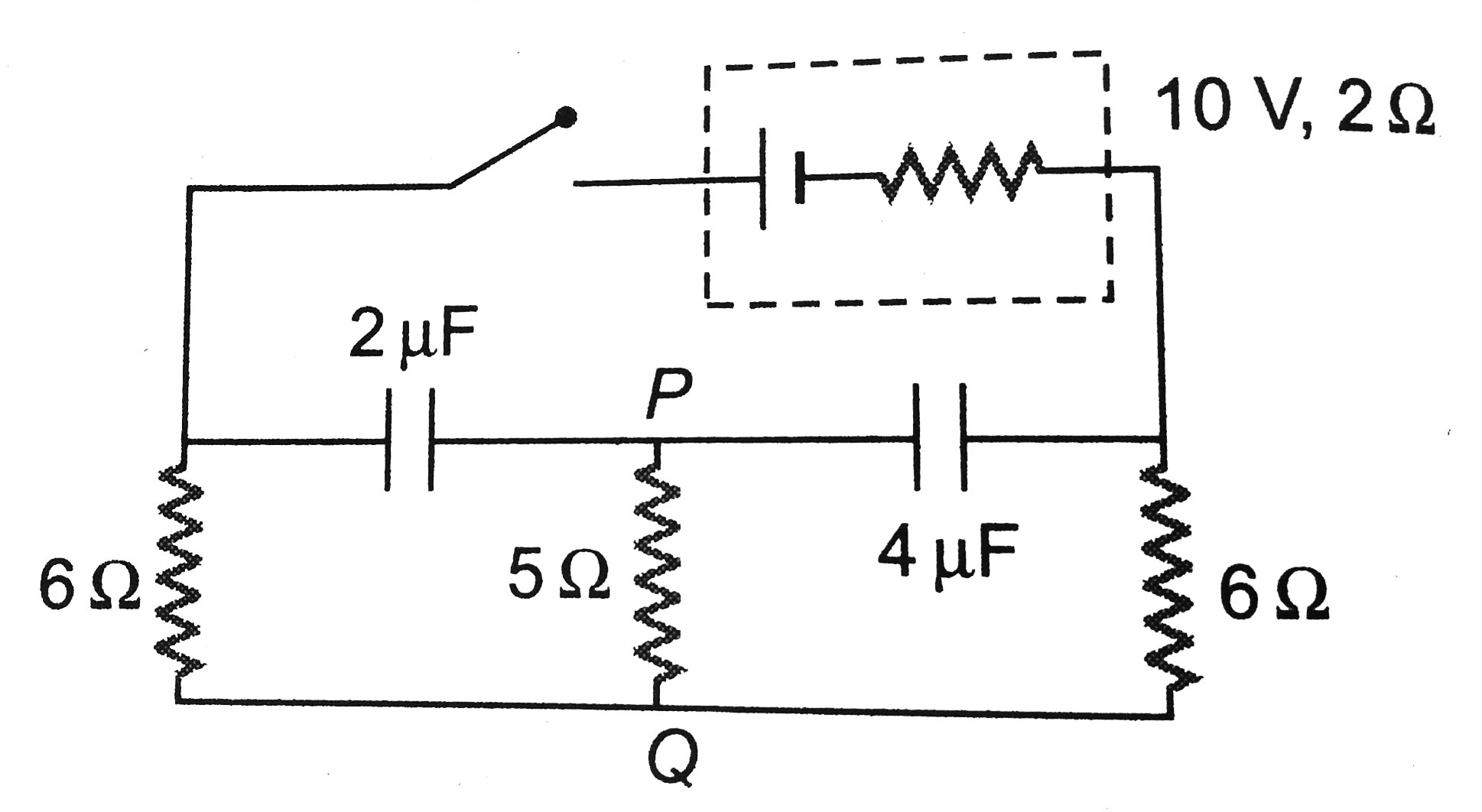 A2A from P to QB2A from Q to PC6A from P to QDzero
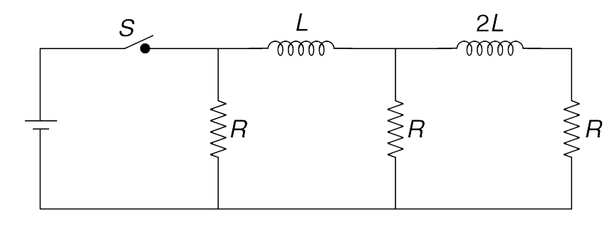
In the circuit shown in figure, the current through each resistor is I. Find the currents through the resistors immediately after the switch ‘S’ is opened. How much heat will get dissipated in the circuit after thw switch is opened ?
View SolutionThe circuit consists of two resistors (of resistance R1=20Ω and R2=10Ω), a capacitor (of capacitance C=10μF) and two ideal cells. In the circuit shown the capacitor is in steady state and the switch S is open
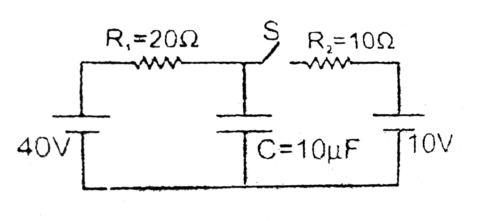
The current through the resistor R2 just after the switch S is closed is :
View SolutionIn the circuit as shown in figure the switch is closed at t=0.
At the instant of closing the switch
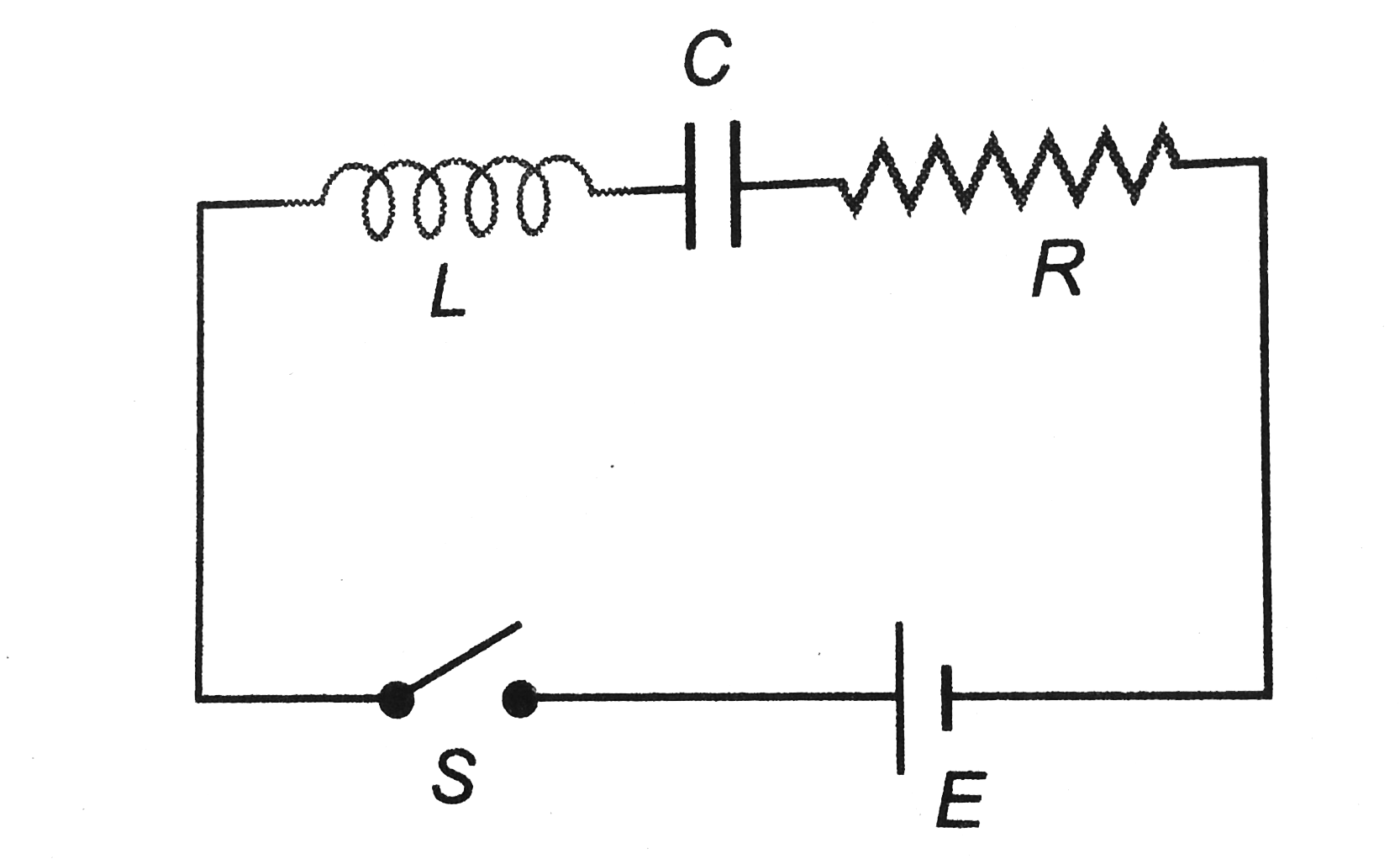
View SolutionWhen the switch S is closed at t=0, identify the correct statement just after closing the switch as shown in figure
View SolutionIn the circuit as shown in figure the switch is closed at t=0.
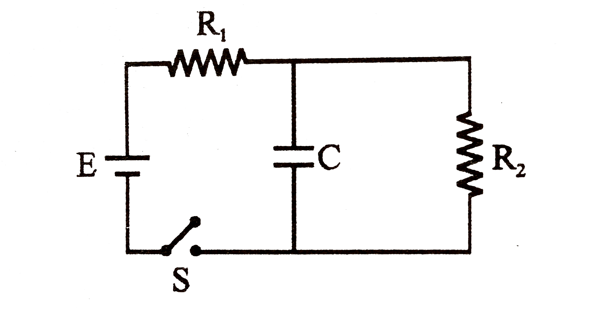
A long time after closing the switch
View Solution
