The emf E and the internal resistance r of the battery shown in figure are 4.3V and 1.0Ω respectively. The external resistance R is 50Ω. The resistances of the ammeter and voltmeter are 2.0Ω and 200Ω respectively.
(a) Find the readings of the two meters.
(b) The switch is thrown to the other side. What will be the readings of the two meters now?
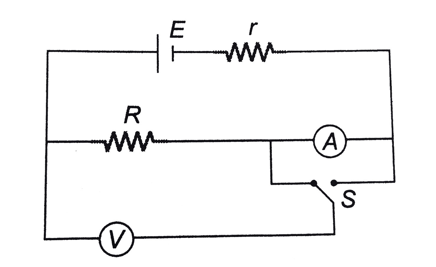
Step by step video & image solution for The emf E and the internal resistance r of the battery shown in figure are 4.3 V and 1.0 Omega respectively. The external resistance R is 50 Omega. The resistances of the ammeter and voltmeter are 2.0 Omega and 200 Omega respectively. (a) Find the readings of the two meters. (b) The switch is thrown to the other side. What will be the readings of the two meters now? by Physics experts to help you in doubts & scoring excellent marks in Class 12 exams.
Updated on:21/07/2023Topper's Solved these Questions
Similar Questions
The emf (ε)and the internal resistance r of the battery shown in figure are 4.3V and 1.0(Ω)respectively.the external resistance R is 50(Ω).The resistances of the ammeter and voltmeter are 2.0(Ω)and 200(Ω)respectively.(a)Find the reading of the two meters.(b) Tje switch is thrown to the other side, What will be the readings of the two meters now?
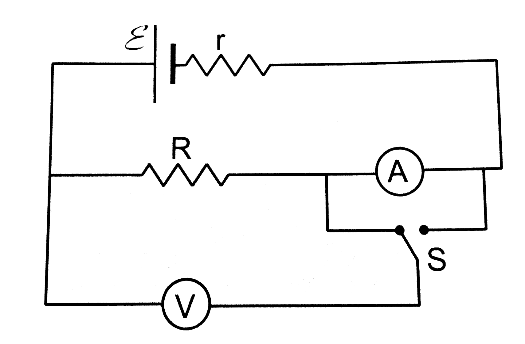
View SolutionThe emf E and the internal resistance r of the battery shown in figure are 4.3V and 1.0Ω respectively. The external resistan ce R is 50Ω. The resistance of the ammeter and voltameter are 2.0Ω an d 200Ω respectively. Find the respective reading of the voltmeter.

View Solution
Knowledge Check
The voltmeter in figure has a resistance of 200Ω. The reading of voltmeter is
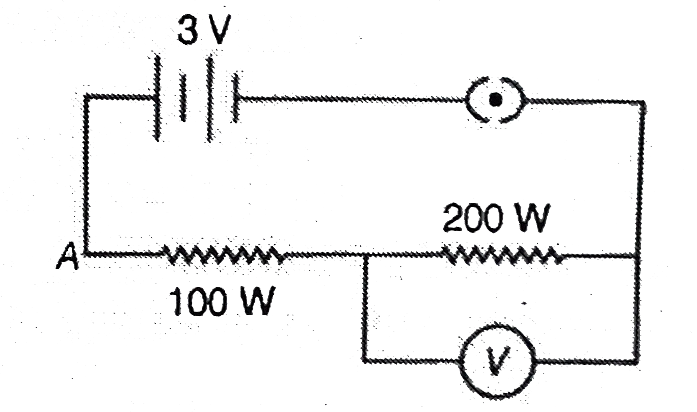 A2 VB1 VC1.5 VD3 V
In the circuit shown in figure ammeter and voltmeter are ideal. If E=4V,R=9Ω and r=1Ω then readings of ammeter and voltmeter are
 A1A,3VB2A,3VC3A,4VD4A,4V
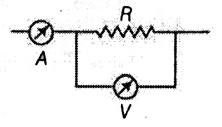
In the adjoining circuit diagram, the readings of ammeter and voltmeter are 2 A and 120 V, respectively. If the value of R is 75Ω, then the voltmeter resistance will be
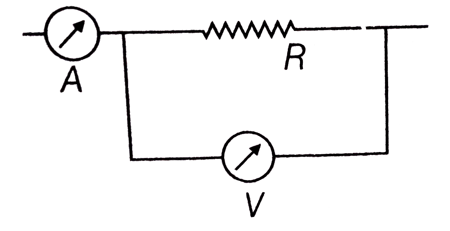 A100ΩB150ΩC300ΩD75Ω
The resistance in the two arms of the meter bridge are 5Ω and RΩ, respectively. When the resistance R is shunted with an equal resistance, the new balance point is 1.6l1.
The resistance R is
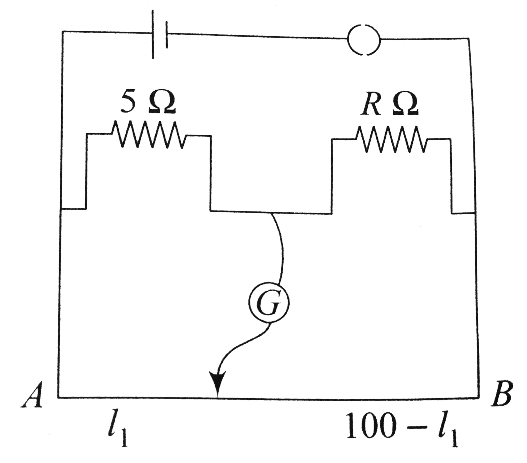
View SolutionThe resistance in the two arms of the meter bridge are 5Ω and RΩ, respectively. When the resistance R is shunted with an equal resistance, the new balance point is 1.6l1.
The resistance R is

View SolutionIf resistance of voltmeter is 10000Ω and resistance of ammeter is 2Ω then find R when voltmeter reads 12 V and ammeter reads 0.1 A
View SolutionA battery of EMF E produces currents 4 A and 3 A when connected to external resistance 1Ω and 2Ω respectively. The internal resistance of the battery is
View SolutionFor the adjoining circuit diagram, the readings of ammeter and voltmeter are 2A and 120 V respectively. If the value of R is 75Ω, then the voltmeter resistance will be
View Solution
