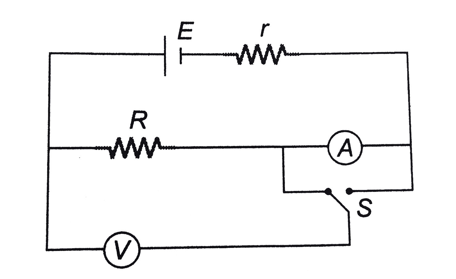
The emf E and the internal resistance r of the battery shown in figure are 4.3V and 1.0Ω respectively. The external resistan ce R is 50Ω. The resistance of the ammeter and voltameter are 2.0Ω an d 200Ω respectively. Find the respective reading of the voltmeter.

The equivalen t resistance of parallel combination of R and voltmeter RP=50×20050+200=50Ω
Total resistance of circuit =RP+2+1=40+2+1=43Ω
Current in the circuit I=4.343=110=0.1A Reading of Ameter
Readin g of voltmeter=0.1×40=4 volt.
Topper's Solved these Questions
Similar Questions
The emf E and the internal resistance r of the battery shown in figure are 4.3V and 1.0Ω respectively. The external resistance R is 50Ω. The resistances of the ammeter and voltmeter are 2.0Ω and 200Ω respectively.
(a) Find the readings of the two meters.
(b) The switch is thrown to the other side. What will be the readings of the two meters now?
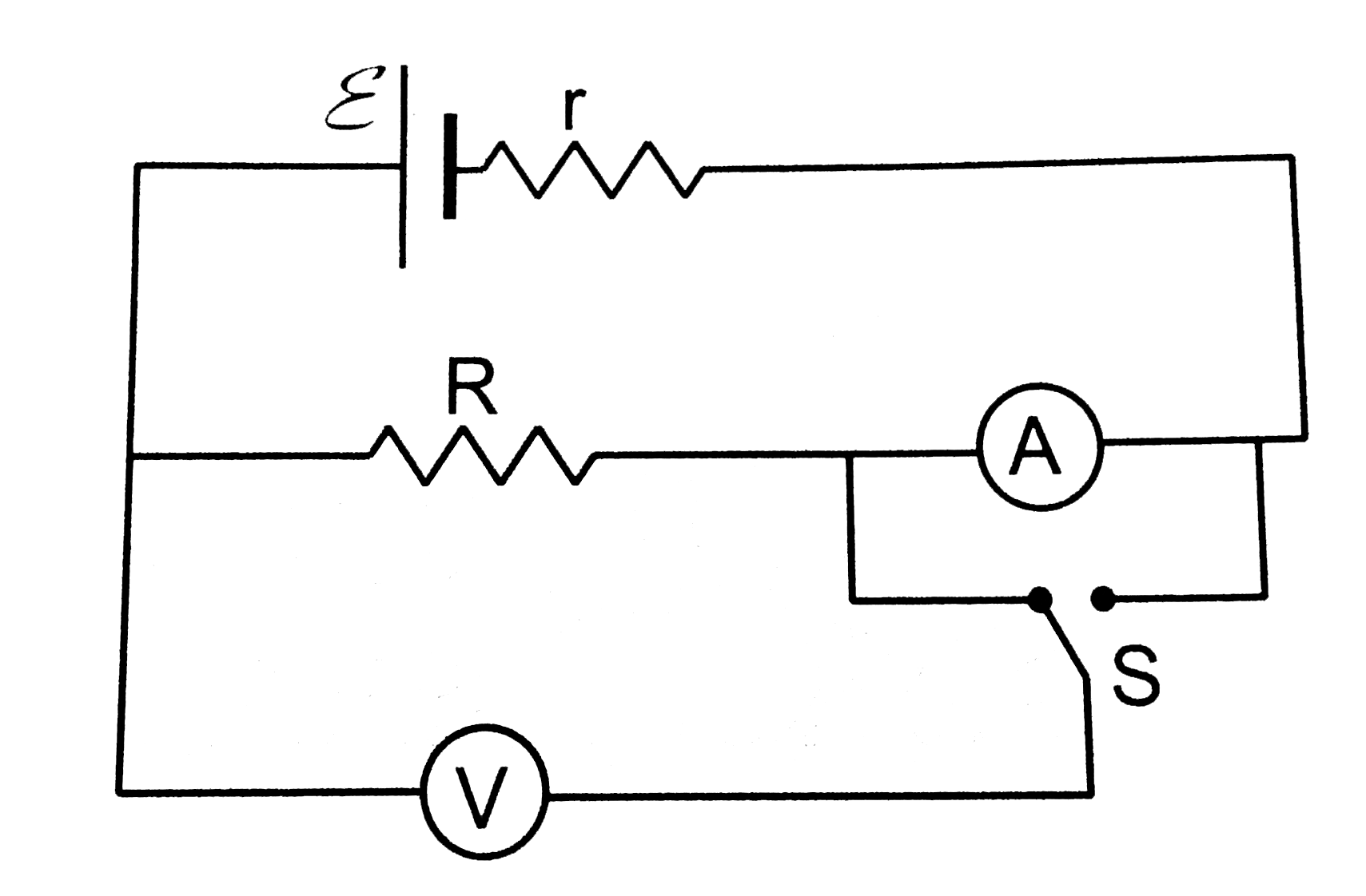
View SolutionThe emf (ε)and the internal resistance r of the battery shown in figure are 4.3V and 1.0(Ω)respectively.the external resistance R is 50(Ω).The resistances of the ammeter and voltmeter are 2.0(Ω)and 200(Ω)respectively.(a)Find the reading of the two meters.(b) Tje switch is thrown to the other side, What will be the readings of the two meters now?
View Solution
Knowledge Check
In the circuit shown in figure ammeter and voltmeter are ideal. If E=4V,R=9Ω and r=1Ω then readings of ammeter and voltmeter are
 A1A,3VB2A,3VC3A,4VD4A,4V
A cell of e.m.f. 2V and negligible internal resistance is connected to resistor R1 and R2 as shown in the figure. The resistance of the Voltmeter R1 and R2 are 80Ω,40Ω and 80Ω respectively. The reading of the voltmeter is:-
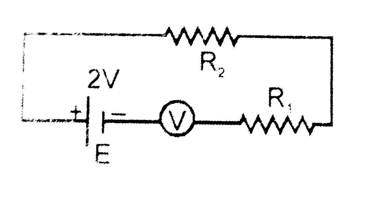 A1.78VB1.60VC0.80VD1.33V
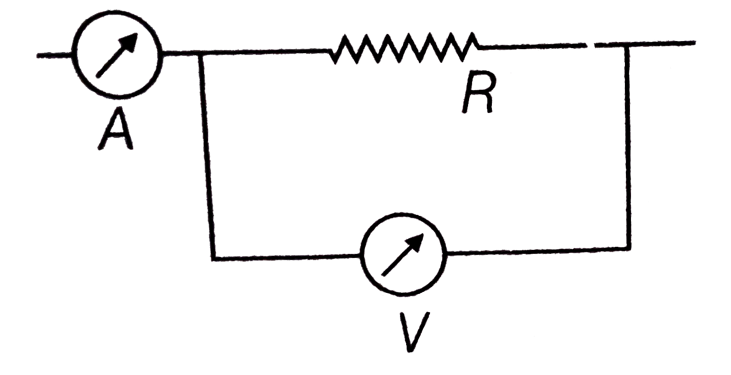
For the adjoining circuit diagram, the readings of ammeter and voltmeter are 2A and 120 V respectively. If the value of R is 75Ω, then the voltmeter resistance will be
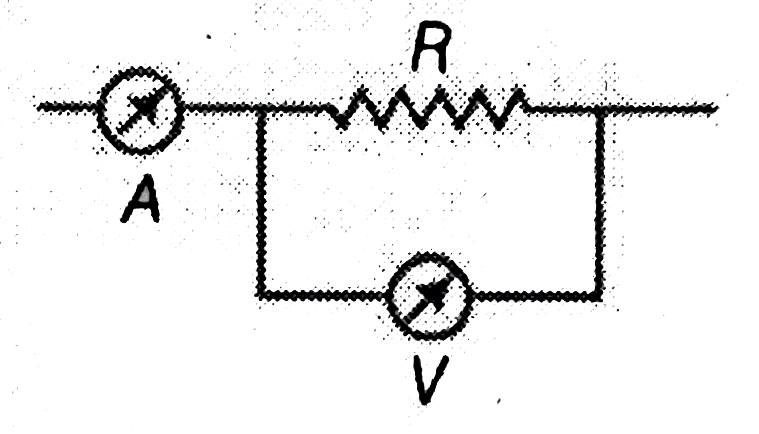 A100ΩB150ΩC300ΩD75Ω
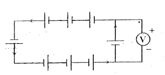
in the circuit shown in the figure, each battery is of 5 V and has an internal resistance of 0.2 Omega What is the reading of the ideal voltmeter V
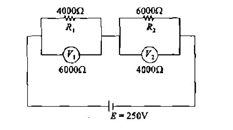
View SolutionIn the circuit shown in figure-3.391, V1andV2 are two voltmeters having resistances 6000Ωand4000Ω respectively EMF of battery is 250V, having negligible internal resistance. Two resistances R1andR2 are 4000Ωand6000Ω respectively. Find the reading of the voltamter V1andV2 when
(a) Switch S is open ltbgt (b) Switch S is closed

View SolutionA cell of emf 3.4V and internal resistance 3Ω is connected to an ammeter having resistance 2Ω and to an external resistance of 100Ω. When a voltmeter is connected across the 100Ω resistance, the ammeter reading is 0.04A. Find the voltage reading by the voltmeter and its resistance. Had the voltmeter been an ideal one what would have been its reading?
View SolutionIn the adjoining circuit diagram, the readings of ammeter and voltmeter are 2 A and 120 V, respectively. If the value of R is 75Ω, then the voltmeter resistance will be
View Solution
