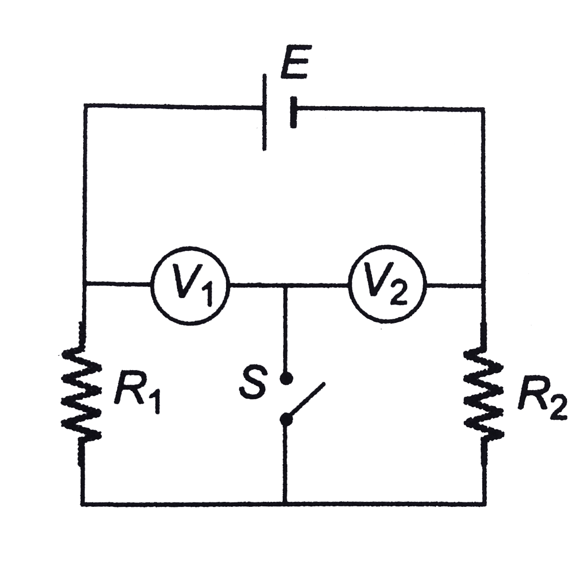
In the circuit shownin figure V1 and V2 are two voltmeter of resistances 3000Ω and 2000Ω respectively. In additions R1=2000Ω, R2=3000ω and E=200V then
a. Fid the reading of voltmeters V1 and V2 when
i. switch S is open
ii. Switch S is closed
b. Current through S, when it is closed (Disregard the resistance of battery)
Step by step video & image solution for In the circuit shownin figure V_1 and V_2 are two voltmeter of resistances 3000 Omega and 2000 Omega respectively. In additions R_1=2000Omega, R_2=3000omega and E=200 V then a. Fid the reading of voltmeters V_1 and V_2 when i. switch S is open ii. Switch S is closed b. Current through S, when it is closed (Disregard the resistance of battery) by Physics experts to help you in doubts & scoring excellent marks in Class 12 exams.
Updated on:21/07/2023Topper's Solved these Questions
Similar Questions
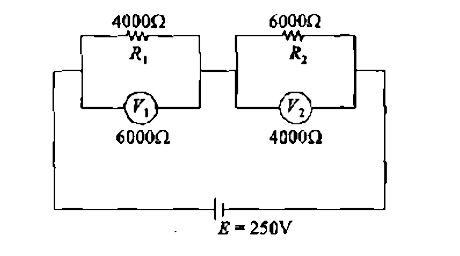
In the circuit shown in figure-3.391, V1andV2 are two voltmeters having resistances 6000Ωand4000Ω respectively EMF of battery is 250V, having negligible internal resistance. Two resistances R1andR2 are 4000Ωand6000Ω respectively. Find the reading of the voltamter V1andV2 when
(a) Switch S is open ltbgt (b) Switch S is closed
View SolutionIn the circuit shown in figure-3.391, V1andV2 are two voltmeters having resistances 6000Ωand4000Ω respectively EMF of battery is 250V, having negligible internal resistance. Two resistances R1andR2 are 4000Ωand6000Ω respectively. Find the reading of the voltamter V1andV2 when
(a) Switch S is open ltbgt (b) Switch S is closed

View Solution
Knowledge Check
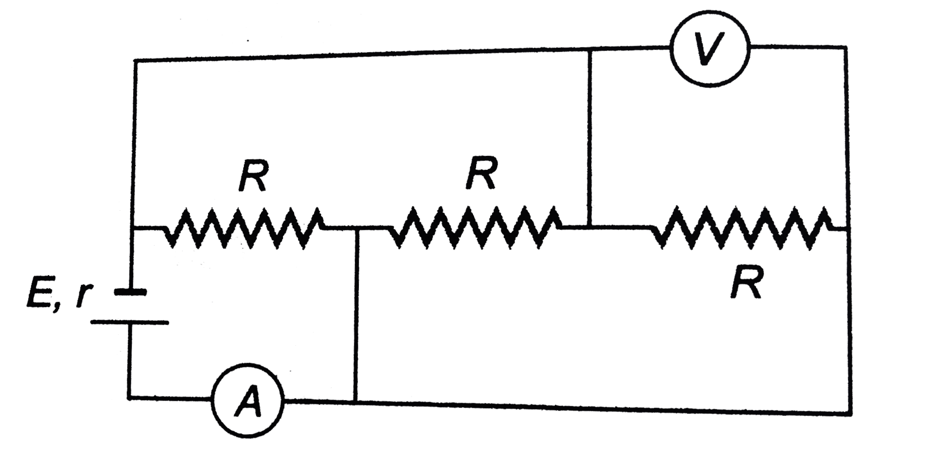
In the circuit shown in figure ammeter and voltmeter are ideal. If E=4V,R=9Ω and r=1Ω then readings of ammeter and voltmeter are
 A1A,3VB2A,3VC3A,4VD4A,4V
A voltmeter has resistance 2000Ω and range 0.5 V. For increasing its range upto 20V, a resistance of
A8000Ω should be connected in series.B6000Ω should be connected in series.C8000Ω should be connected in parallelD6000Ω should be connected in parallel.Resistance of 100Ω and 200Ω are connected in series with 220 V mains. When a voltmeter of 1000Ω resistance is connected in parallel to100Ω , then the reading of voltmeter is
A68.75VB6.87VC584.5VD58.75V
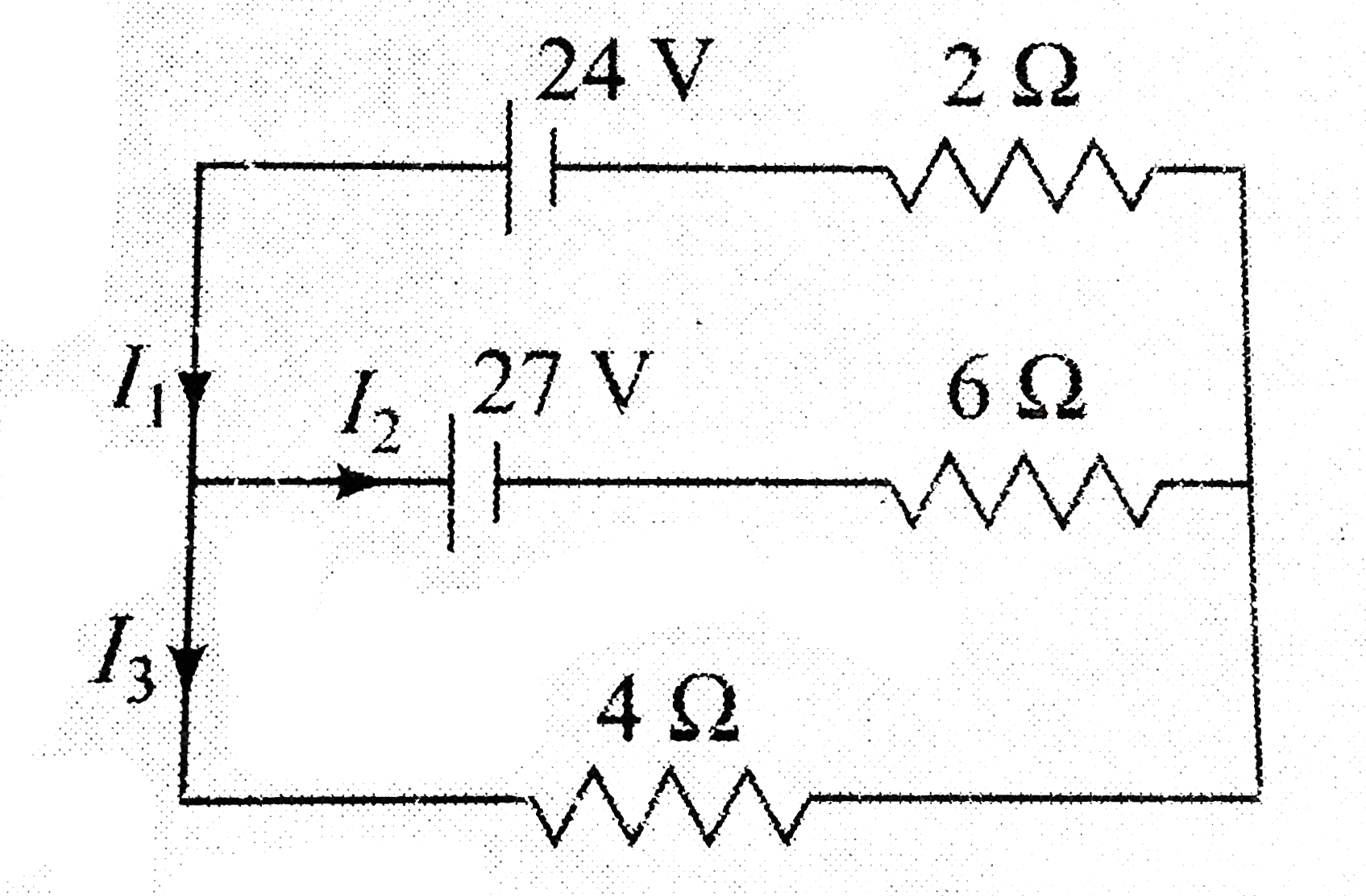
In the circuit, the cells E1andE2 have emfs of 4V and 8V and internal resistance 0.5Ωand1.0Ω, respectively. Calculate the current through 6Ω resistance.
View SolutionIn the circuit shown in the figure, cell is ideal and R2=100Ω. A voltmeter of internal resistance 200Ω reads V12=4VandV23=6V between the pair of points 1−2and2−3 respectively. What will be the reading of the voltmeter between the points 1−3.

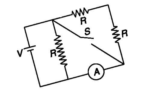
View SolutionIn the circuit shown, R=2ΩandV=20 volt. With switch S open the reading of ammeter is half its reading when ‘S’ is closed. Calculate the resistance of the ammeter.
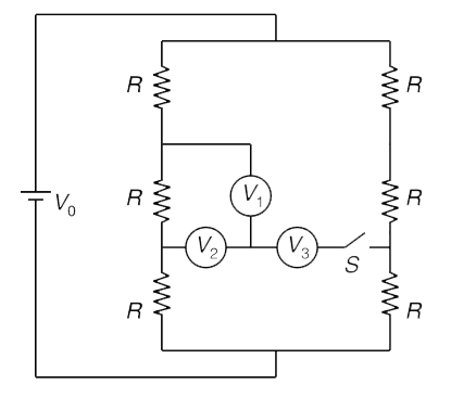
View SolutionIn the circuit shown in figure all resistances are identical (each equal to R) and the cell has an emf of V0. The three voltmeters V1,V2andV3 are identical and are nearly ideal.
(a) find the reading of the voltmeter V1 when switch ‘S’ is open.
(b) find the reading of the voltmeter V1 after the switch is closed
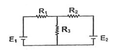
View SolutionIn the circuit shown, E1=7V,E2=7V,R1=R2=1Ω and R3=3Ω respectively. The current through the resistance R3
View Solution

