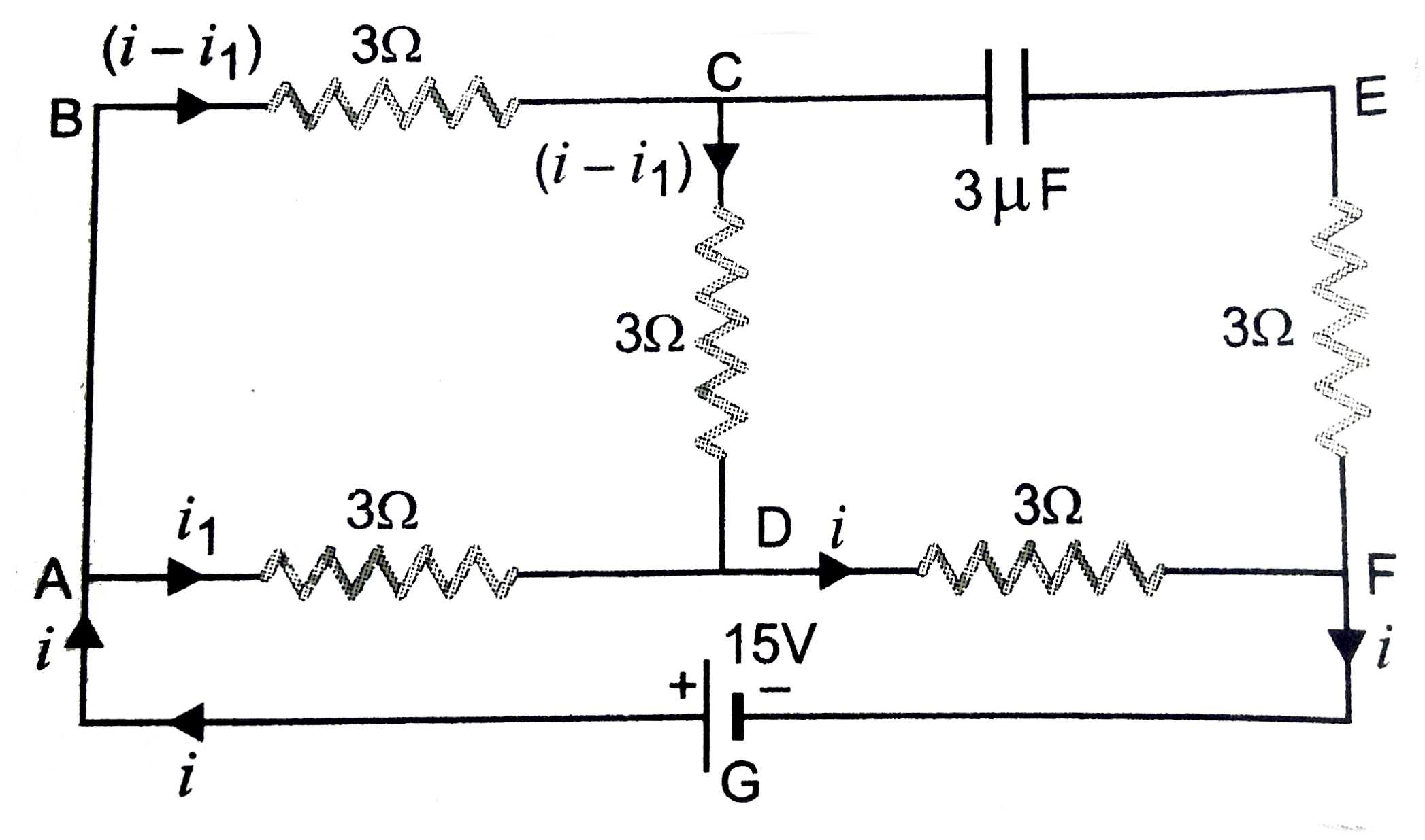
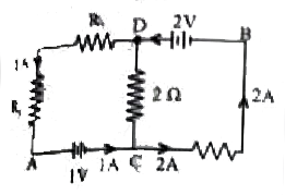
Consider the circuit shown in the figure. Taking the potential to be zero at the negative terminal of the battery :
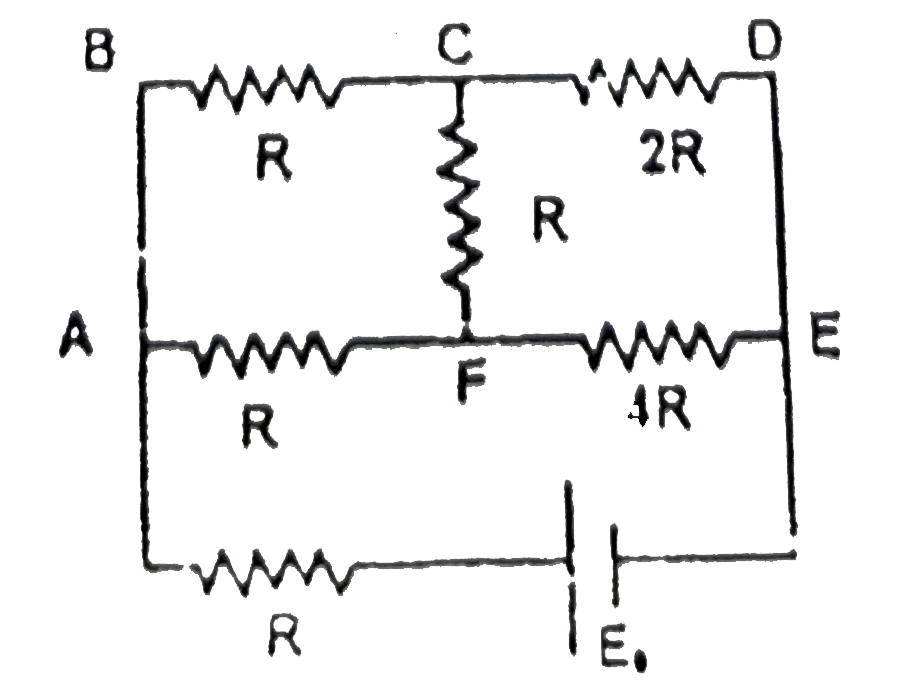
Potential at will be higher than the potential at
Current in will be greater than that in
Direction of current in will be from to
Current in will be greater than current in
( at point )
…..() ()
Aiso …….()
Using () & ()
Topper's Solved these Questions
- GMP ASSESMENTBook:FIITJEEChapter:GMP ASSESMENTExercise:Assertion & Reason
Explore 15 Videos
- GMP ASSESMENTBook:FIITJEEChapter:GMP ASSESMENTExercise:Multiple Question
Explore 58 Videos
- GMP ASSESMENTBook:FIITJEEChapter:GMP ASSESMENTExercise:Numerical Based
Explore 61 Videos
- GENERAL PHYSICSBook:FIITJEEChapter:GENERAL PHYSICSExercise:MATRIX MATCH TYPE
Explore 3 Videos
- GRAVITATIONBook:FIITJEEChapter:GRAVITATIONExercise:Numerical based Question
Explore 2 Videos
Similar Questions
Knowledge Check
Consider the circuit shown in the following figure.
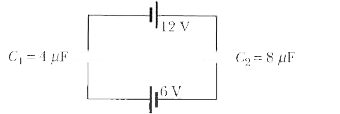 AThe charge on C2 is greater than on C1BThe charge on C1andC2 are the sameCThe potential drops across C1andC2 are the sameDThe potential drops across C1 is greater than that across C2
In a circuit shown in the figure, what is potential of point A?
 A2VB5VC8VD4V
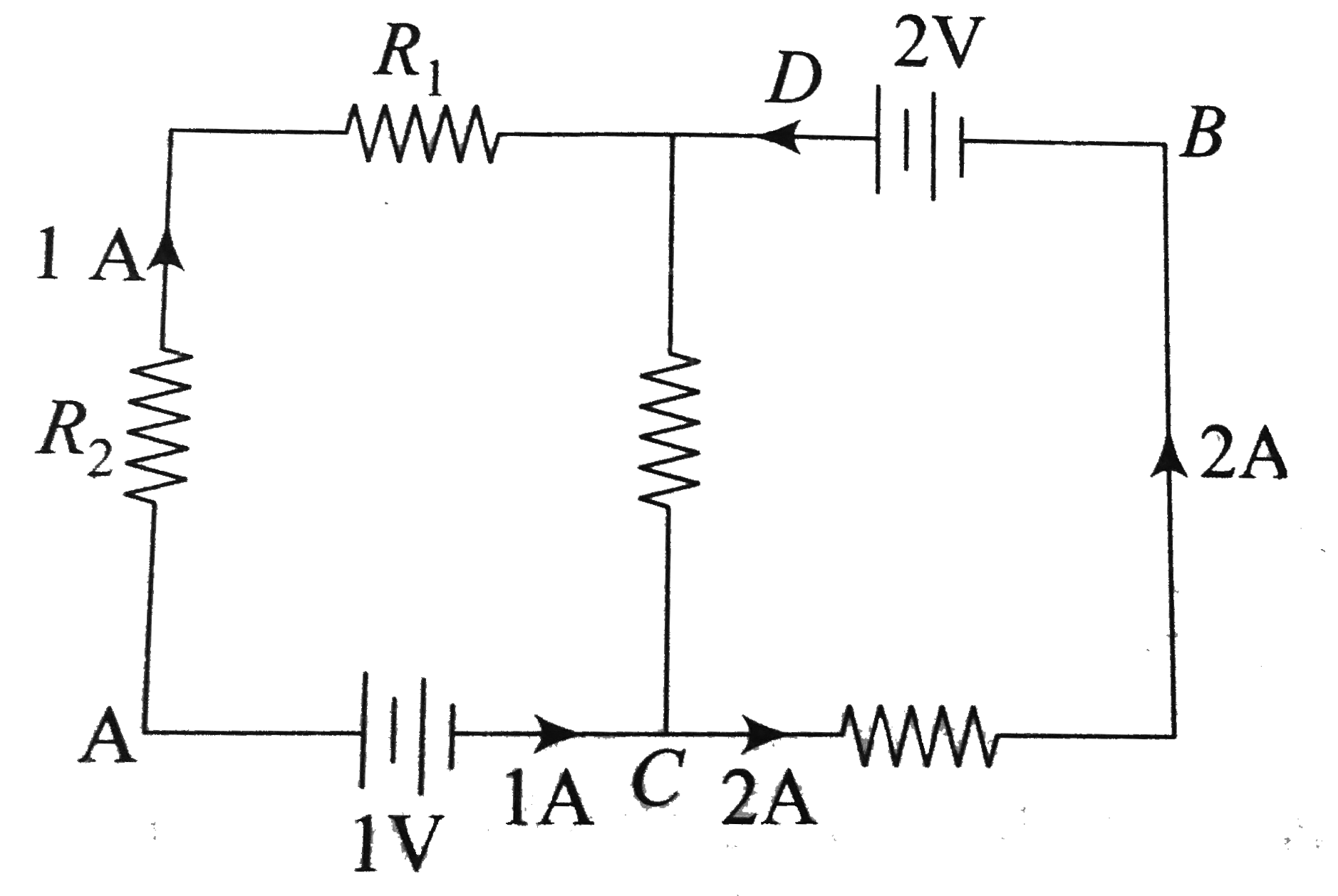
In the circuit shown in the figure, if the potential at point A behind to be zero, the potential at point B is :
 A−1VB+2VC−2VD+1V
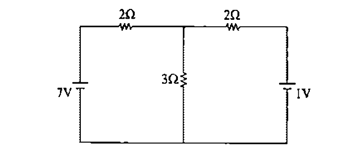
In the circuit shown in figure-3.205 find the power supplied by the two batteries.
View SolutionA 6V battery of negligible internal resistance is connected across a uniform wire AB of length 100cm. The positive terminal of another battery of emf 4V and internal resistance 1Ω is joined to the point A as shown in figure. Take the potential at B to be zero.
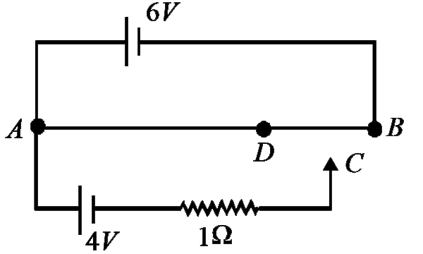
2What are the potentials at points A and C ?
View SolutionIn the circuit shown in the figure, if potentail at point A is taken to be zero, the potential at point B is
View SolutionIn the circuit shown in the figure, in steady state:

The current drawn from the battery is
View SolutionAssertion : In simple battery circuit , the point at the lowest potential is negative terminal of the battery .
Reason : The current flows towards the point of the highest potential , as it does in a circuit from negative to the positive terminal .
View Solution

