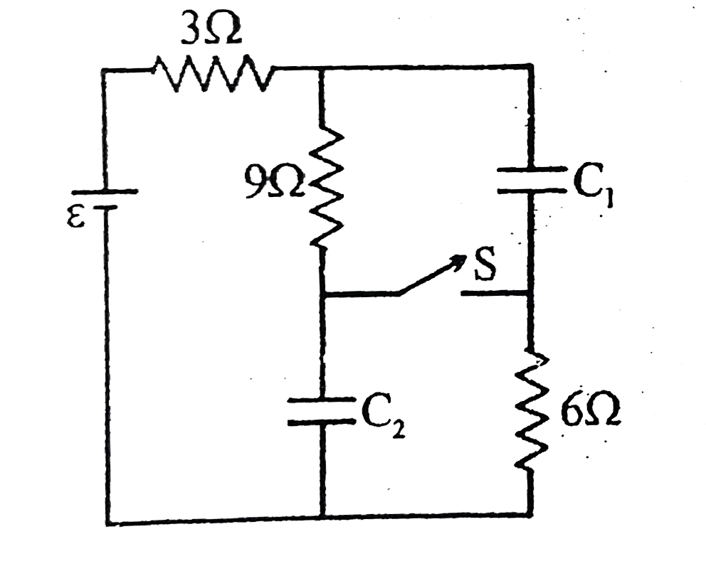
In the circuit shown there is steady state with the switch closed. The switch is opened at t=0 Choose the correct option(s) (Given varepsilon=24V,C_(1)=3Fand C_(2)=2F)

The voltage across C1 before the switch is open is 12V
The voltage across C1 after a long time after the switch is open is 12V
The voltage across C2 after a long time after the switch is open is 24V
The voltage across C2 before the switch is open is 8V
The correct Answer is:A, C, D
i=243+9+6=43A
V1=43×9=12
V2=43×6=8V
at t=∞
V,=V1=24
Topper's Solved these Questions
- MASTER PRACTICE PROBLEMBook:BANSALChapter:MASTER PRACTICE PROBLEMExercise:Subjective
Explore 107 Videos
- MASTER PRACTICE PROBLEMBook:BANSALChapter:MASTER PRACTICE PROBLEMExercise:Additional topic
Explore 70 Videos
- MASTER PRACTICE PROBLEMBook:BANSALChapter:MASTER PRACTICE PROBLEMExercise:Reasoning
Explore 75 Videos
- FLUID MECHANICSBook:BANSALChapter:FLUID MECHANICSExercise:PYQS AIEEE
Explore 10 Videos
- SEMICONDUCTORSBook:BANSALChapter:SEMICONDUCTORSExercise:CBSE Question
Explore 32 Videos
Similar Questions
In a given system of unit standard measurement of mass is 100 gm standard measurement of length is 200 cm and standard measurement of time is 5 sec 10 J energy in the given system of unit has value N, then value of N is
View SolutionThe manifestation of band structure in solids is due to
View SolutionStatement-1: The numerical value (n)of a physical quantity is inversely proportional to size of unit (u) being used to measure it.
Statement-2:The magnitude of physical quantity does not change by changing the units.
View SolutionA cylinder of height 20m is completely filled with water. The velocity of effux of water (∈ms−1) through a small hole on the side wall of the cylinder near its bottom is
View SolutionHow does the width of the depletion layer of a p-n junction diode change with decrease in reverse bias?
View SolutionIn the given circuit Fig the switch is closed at t = 0 . Choose the correct answers.
View SolutionIn the circuit shown, the switch 'S' is closed at t = 0 . Then the current through the battery steady state reached is
View SolutionA circuit containing two capacitor C_(1) and C_(2) shown in figure is in steady state with switch K_(1) closed and K_(2) open. At the instant t=0,K_(1) is opened and K_(2) is closed. The correct statements are.
View SolutionInitially the switch 'S' is open for a ling time. Now the switch 'S' is closed at t=0(R_(1)=2Omega, R_(2)=2Omega, C_(1)=1F and C_(2)=1F) Then
View SolutionTwo capacitors C_(1) and C_(2) = 2C_(1) are connected in a circuit with a switch between them as showu in the figure- 3.302. Initially the switch is open and C_(1) holds charge Q. The switch is closed. In steady state, the charge on the two capacitors will be given as :
View SolutionIn the circuit diagram shown in figure, initially switch S is opened and the circuit is in steady state. At time t=0, the switch S is closed and the new steady state is reached after some time. Choose the correct option(s)

View SolutionIn given circuit, switch S is closed at t=0 . The charge on the capacitor ar steady state will be

View SolutionIn the following circuit, the switch S is closed at t = 0. The charge on the capacitor C_(1) as a function of time will be given by (C_(eq)=(C_(1)C_(2))/(C_(1)+C_(2)))
View SolutionIn the following circuit, the switch S is closed at t = 0. The charge on the capacitor C_(1) as a function of time will be given by (C_(eq)=(C_(1)C_(2))/(C_(1)+C_(2)))
View SolutionTwo capacitorsC1andC2=2C1 are connected in a circuit with a switch between them as showu in the figure- 3.302. Initially the switch is open and C1 holds charge Q. The switch is closed. In steady state, the charge on the two capacitors will be given as :

View Solution

