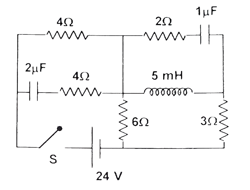
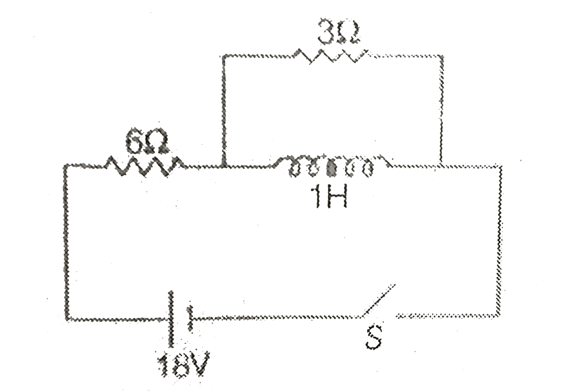
In the circuit shown, the switch 'S' is closed at t=0. Then the current through the battery steady state reached is
A
2A
B
4A
C
6A
D
8A
Video Solution
Text Solution
The correct Answer is:B
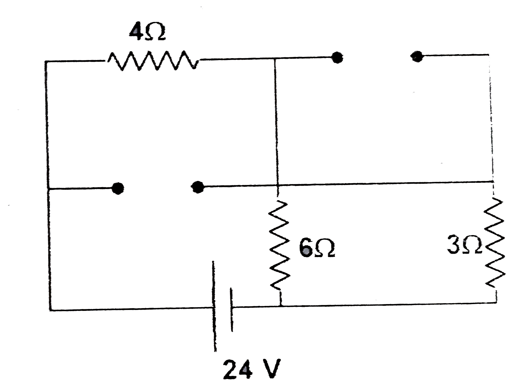
In steady state, the equivalent circuit is shown.
Req=4+(6×36+3)
Req=4+2=6Ω
∴IS=εReq=246=4A
|
Topper's Solved these Questions
- TEST PAPERSBOOK - FIITJEECHAPTER - TEST PAPERSEXERCISE - PHYSICS
747 Videos
- SIMPLE HARMONIC MOTIONBOOK - FIITJEECHAPTER - SIMPLE HARMONIC MOTIONEXERCISE - Assignment Problems (Objective) (Level-II)
20 Videos
- WORK, ENERGY AND POWER BOOK - FIITJEECHAPTER - WORK, ENERGY AND POWER EXERCISE - COMPREHENSIONS ( Comprehension-II)
5 Videos
Similar Questions
Knowledge Check
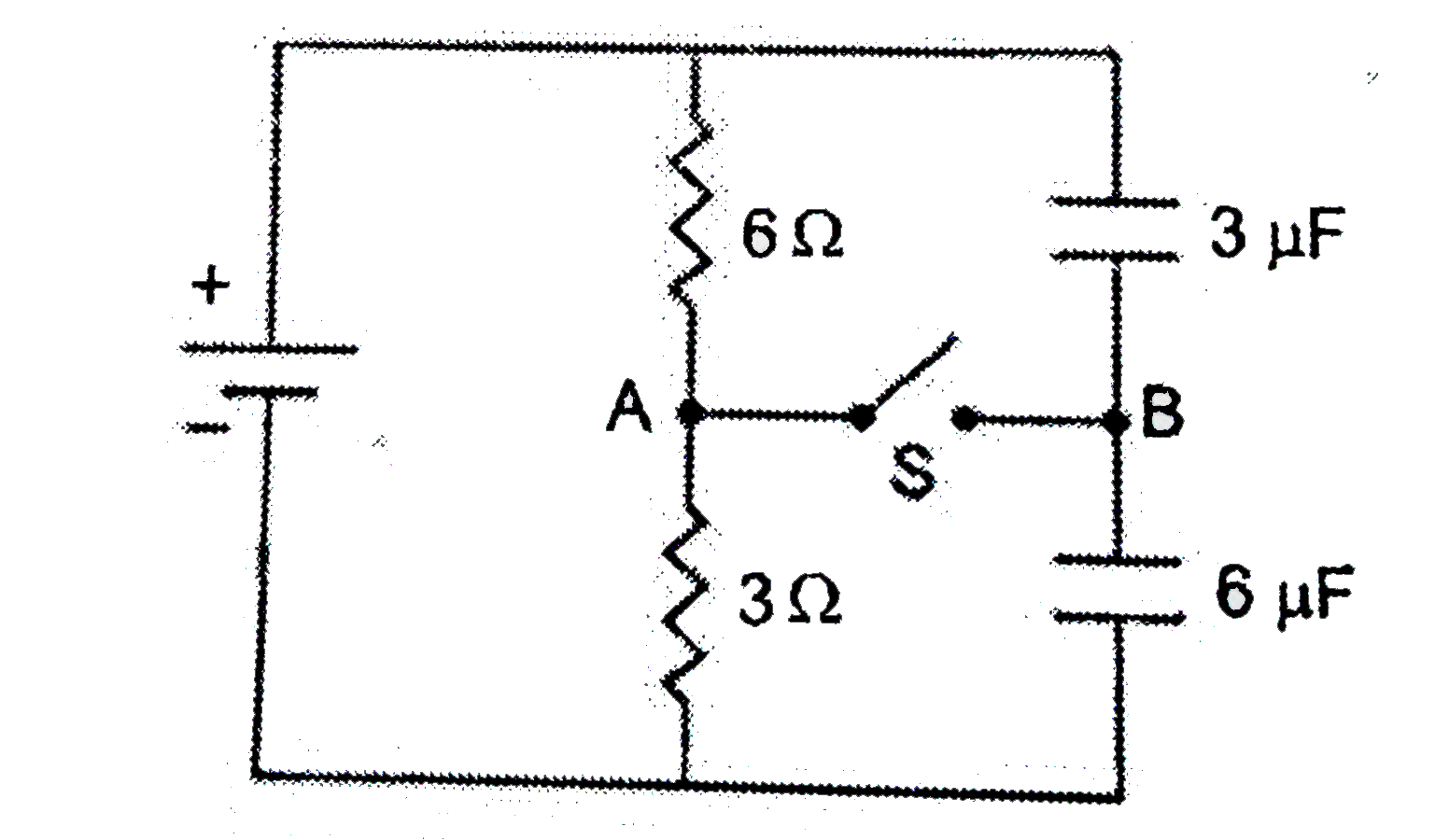
In the circuit shown above, when then switch S is closed,Ano charge flows through SBcharge flows from A to BCcharge flows from B to ADcharge flows initially from A to B and later from B to AIn the circuit shown, the switch is closed at t=0, the currents I1,I2 and I3 are
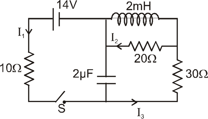 A1.4A,0,0B1.4 A,0.70 A,0.70 AC0,0,0D1.2A,0.6A,0.6A
In the circuit shown if Fig. the switch S is closed at time t = 0. The current through the capacitor and inductor will be equal at time t equal (given R=√L/C
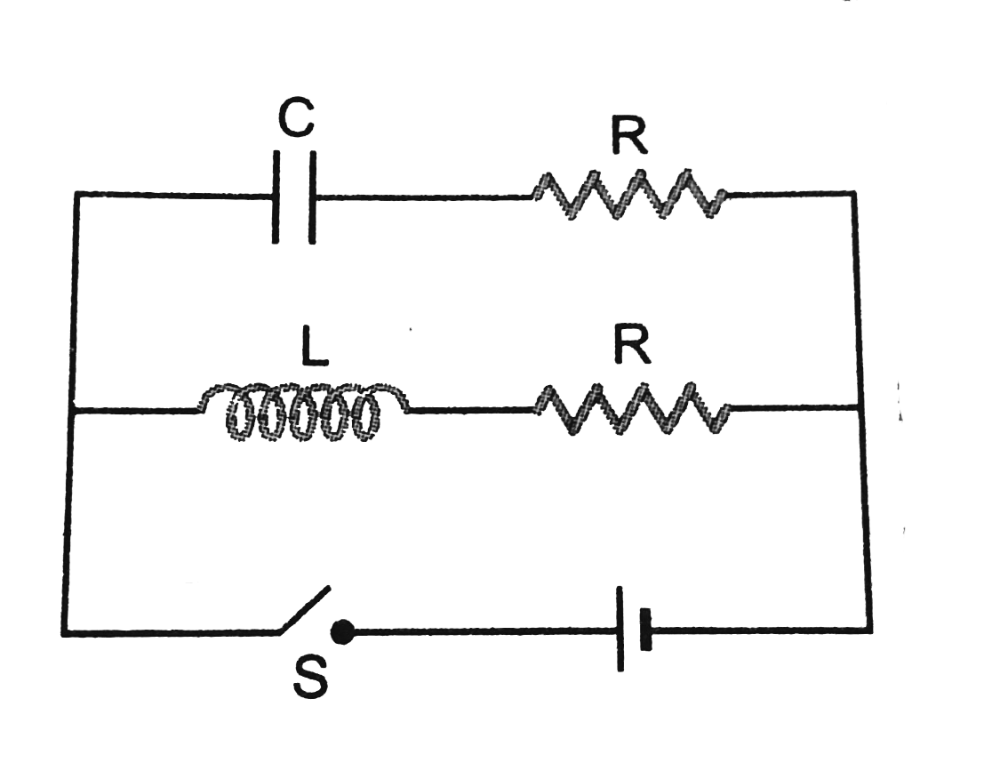 ARCBRCloge2C1RlogeDLR
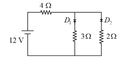
Find the current flowing through the battery in steady state?
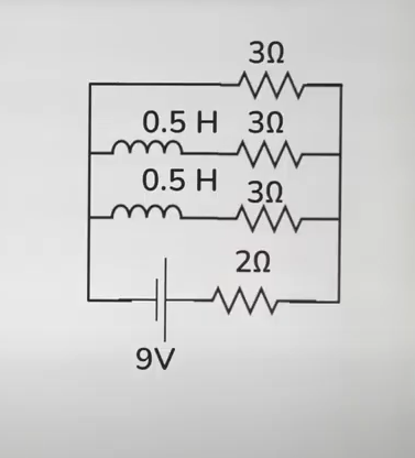
View SolutionThe current through the battery shown in the circuit is
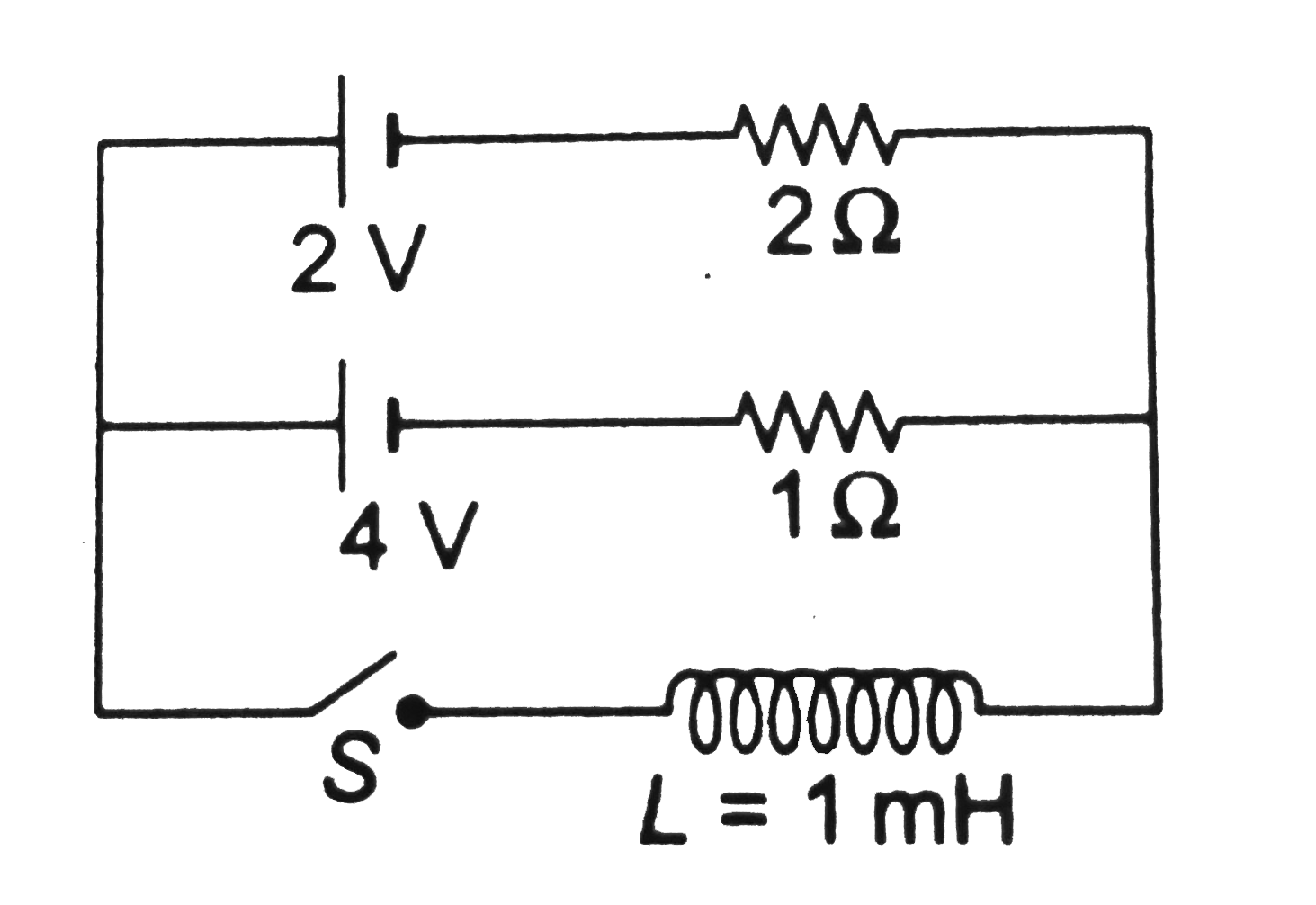
View SolutionIn the circuit shown, switch S is closed at time t=0. Find the current through the inductor as a function of time t.
View SolutionSwitch is closed at t=0 then the current in the circuit at t=L2R is
_PHY_E06_157_Q01.png)
View SolutionIn the circuit shown in figure switch S is closed at time t=0
Current I from the battery at time t is given by
View Solution

