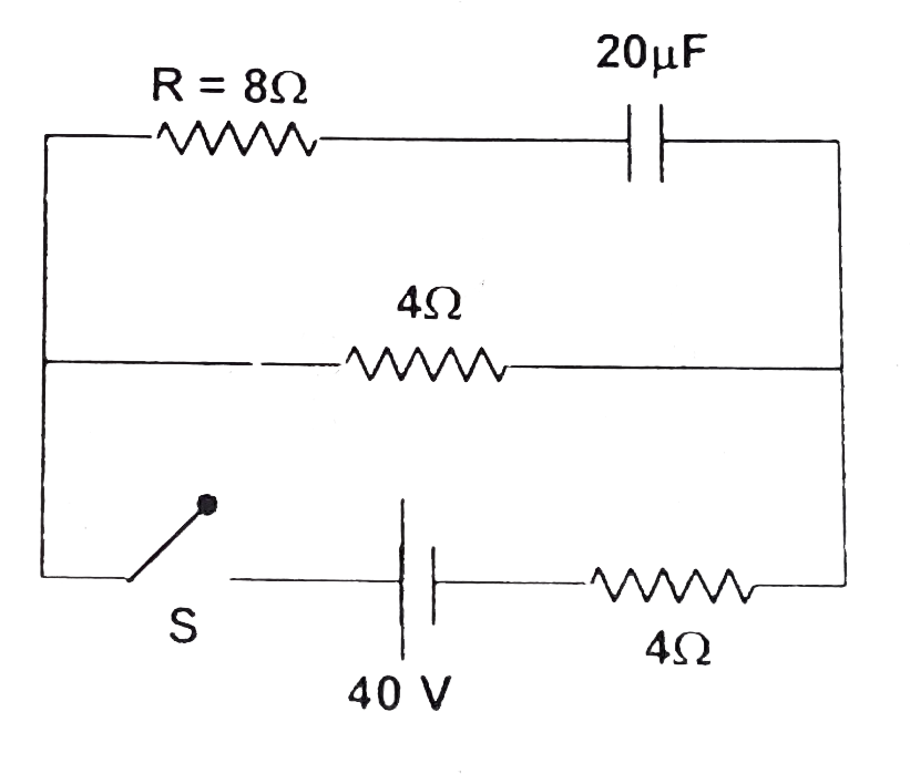
In the circuit shown, the switch 'S' is closed at t=0. Then capacitor is initially uncharged. Then the current through the resistor R=8Ω at t=0.4×10⁻³sec is (Take e−2=0.135 )
A
0.18A
B
0.27A
C
0.54A
D
0.72A
Video Solution
Text Solution
The correct Answer is:B
time constant , τ=ReqCeq
=10×20×10−6
=0.2×10⁻³sec
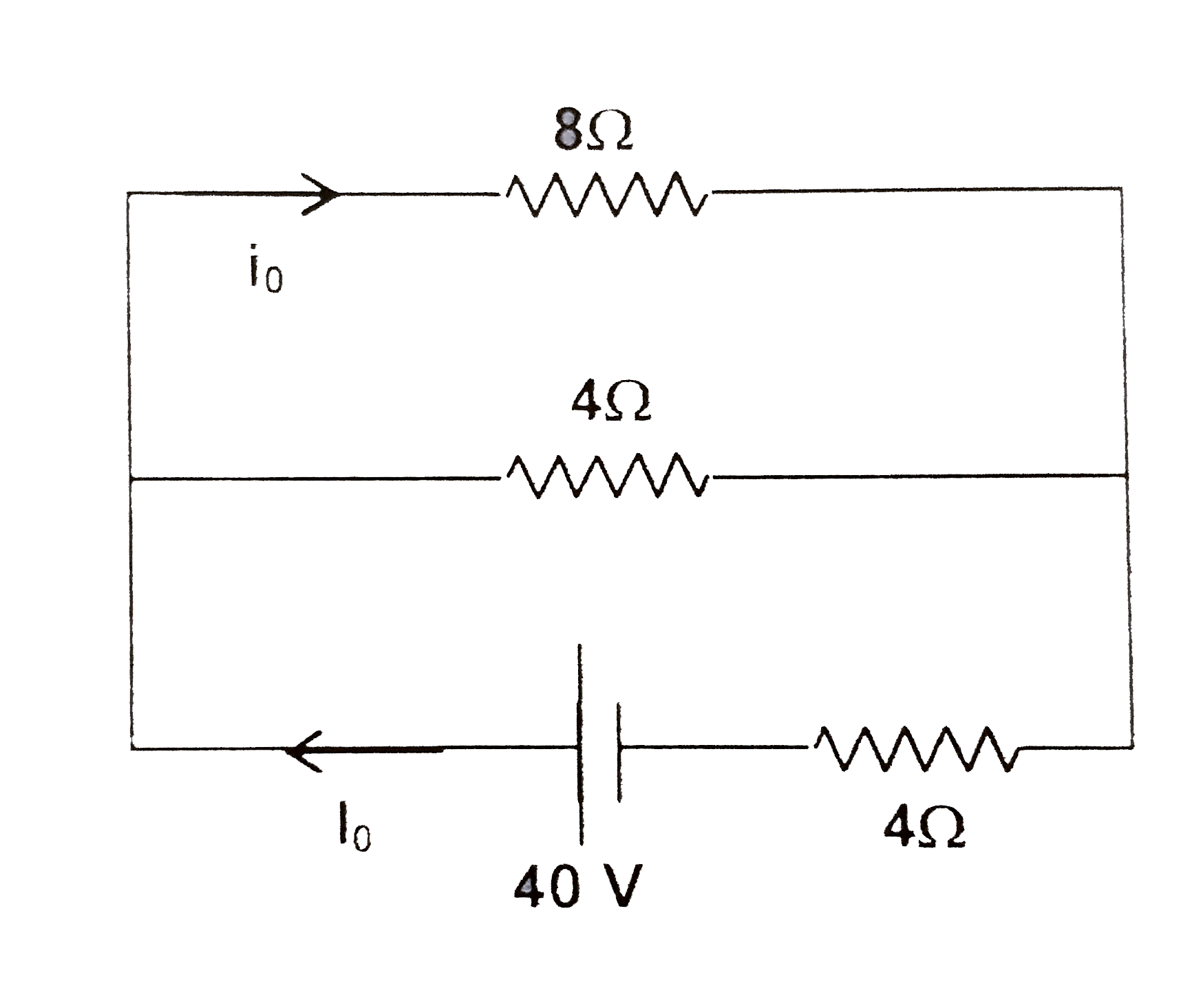
The current through the battery just after closing the witch is I0=40×320=6A
The current through R=8Ω register ate t=0 is
i0=13×I0=13×6=2A
The current through R=8Ω resistor at time 't'
i0=i0e−t/τ
i=2e−t/0.2×10−3
∴att=0.4×10⁻³sec.<br>i = 2e^(-2) = 2 xx 0.135 = 0.27 A
|
Topper's Solved these Questions
- TEST PAPERSBOOK - FIITJEECHAPTER - TEST PAPERSEXERCISE - PHYSICS
747 Videos
- SIMPLE HARMONIC MOTIONBOOK - FIITJEECHAPTER - SIMPLE HARMONIC MOTIONEXERCISE - Assignment Problems (Objective) (Level-II)
20 Videos
- WORK, ENERGY AND POWER BOOK - FIITJEECHAPTER - WORK, ENERGY AND POWER EXERCISE - COMPREHENSIONS ( Comprehension-II)
5 Videos
Similar Questions
Knowledge Check
In the circuit shown key is closed at t=0 with capacitor initially uncharged.
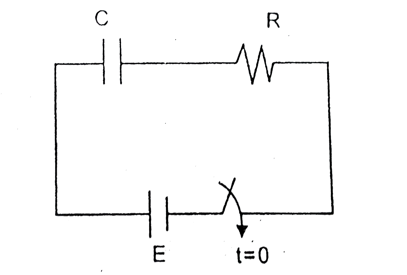 ARate of increase of capacitors energy, just after the switch is closed is E2RBMaximum power supplied by the cell is E2RCAt t=RCIn2, capacitor is charged up to half of the energy stored by it in steady stateDAt t=RCIn2, potential difference across capacitor is same that across resistor.
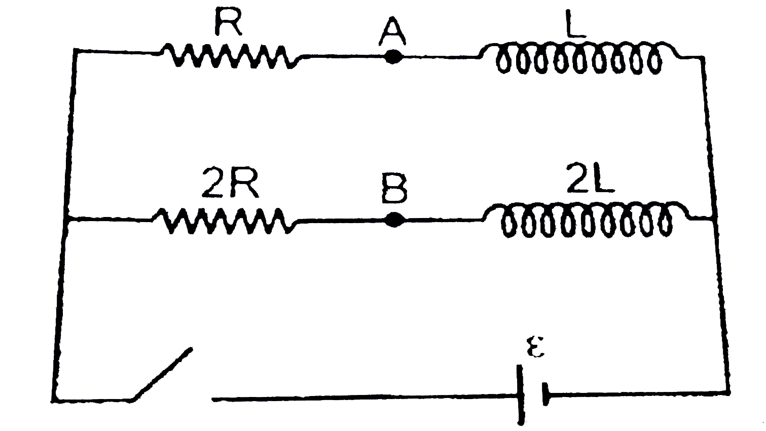
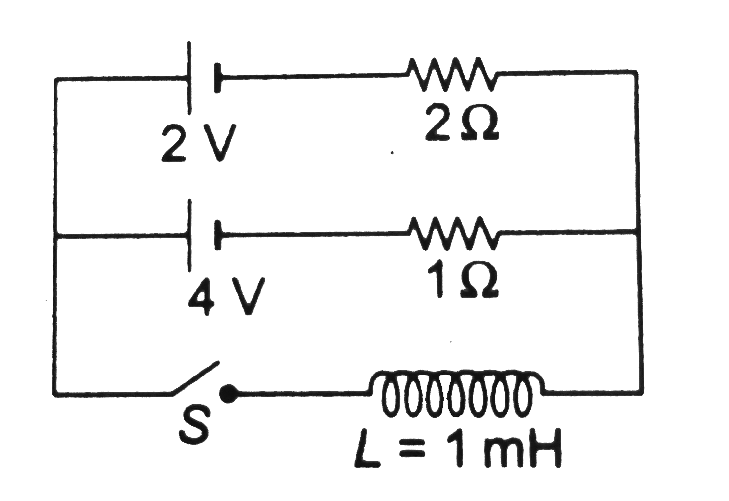
In given LR circuit the switch S is closed at time t=0 thenAThe ratio of induced emfs in the inductors of inductance L and 2L will be constantBThe ratio of induced emfs in the inductor of inductance L and 2L will be time varyingCthe potential difference VA−VB increases with timeDThe potential difference VA−VB will be constantIn the circuit shown in fig, if the switch S is closed at t=0 , the capacitor charges with a time constant
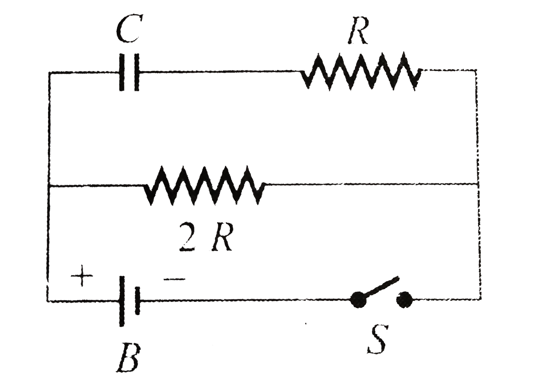 ARCB3RCC23RCDRCIn(23)
In the circuit shown, the switch 'S' is closed at t=0. Then the current through the battery steady state reached is
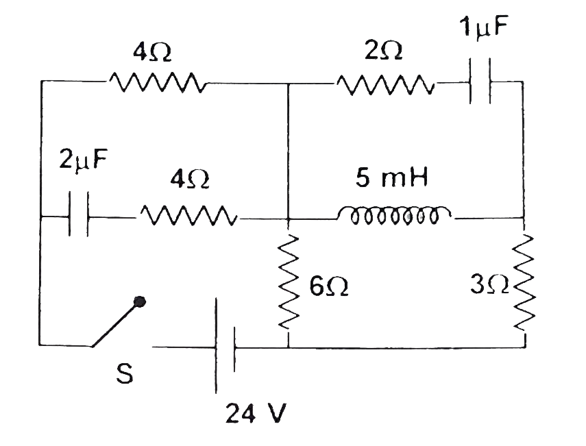
View SolutionIn the circuit shown in figure, the capacitors are initially uncharged. The current through resistor PQ just after closing the switch is
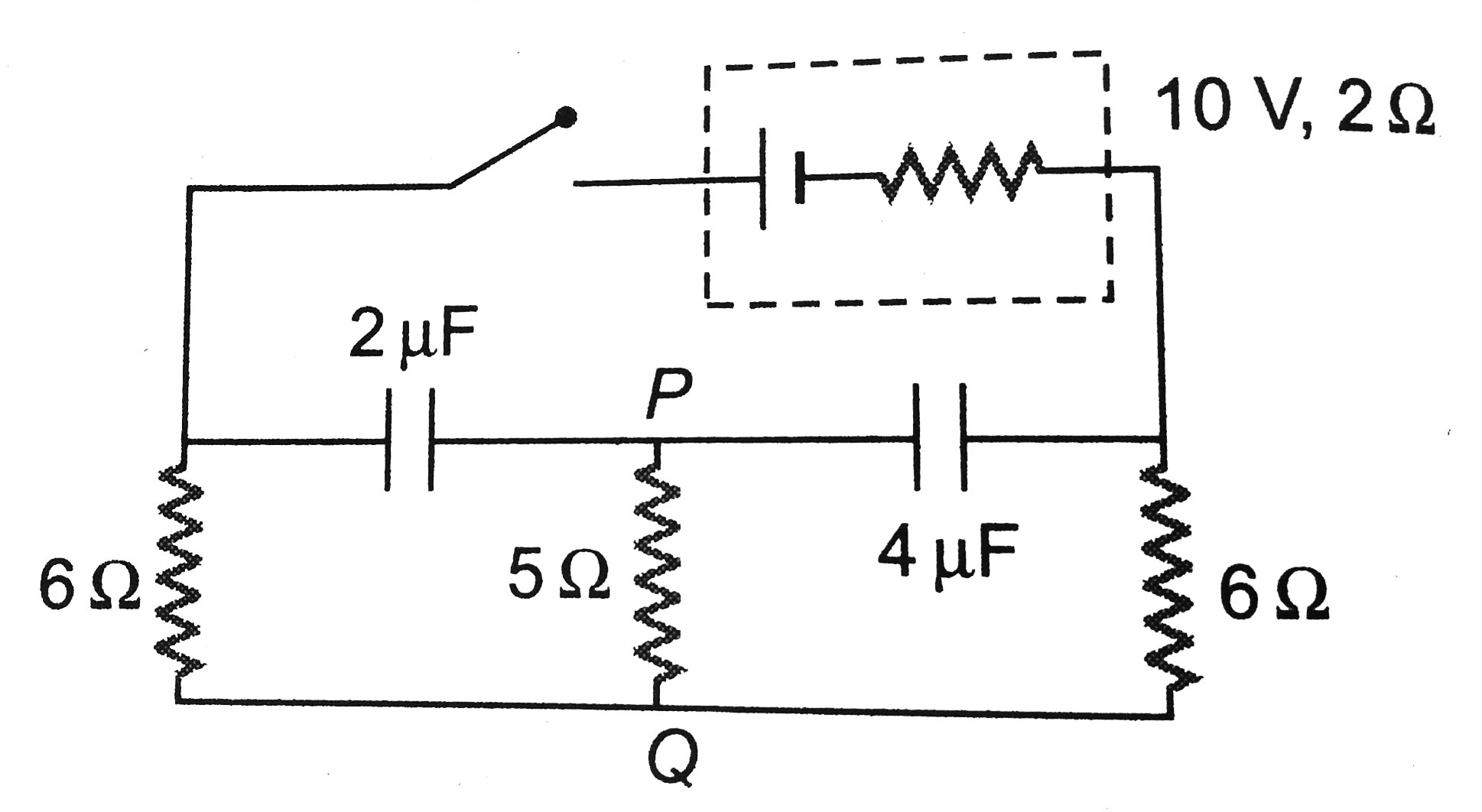
View Solution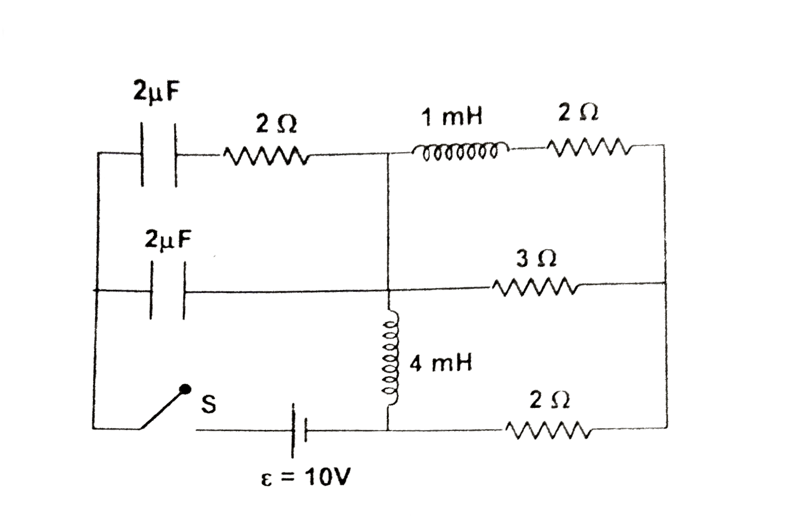
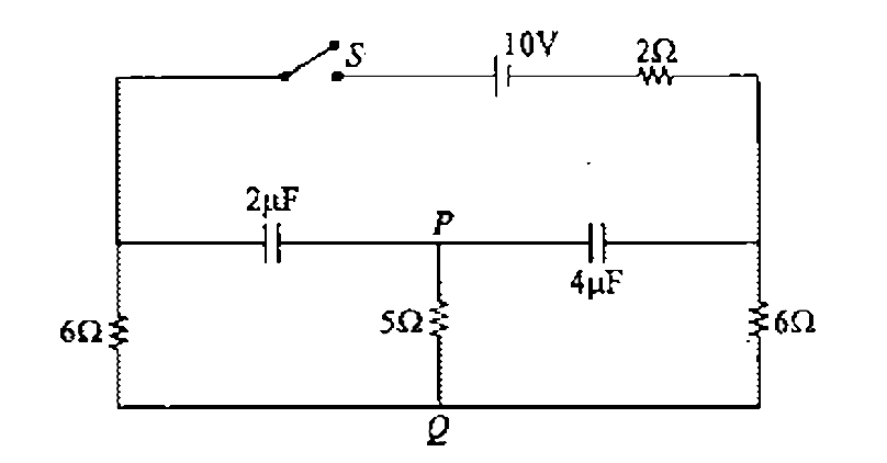
In the circuit shown, all the capacitors are initially uncharged. The current through the battery just after closing the switch 'S' is
View SolutionIn the circuit as shown in figure the switch is closed at t=0.
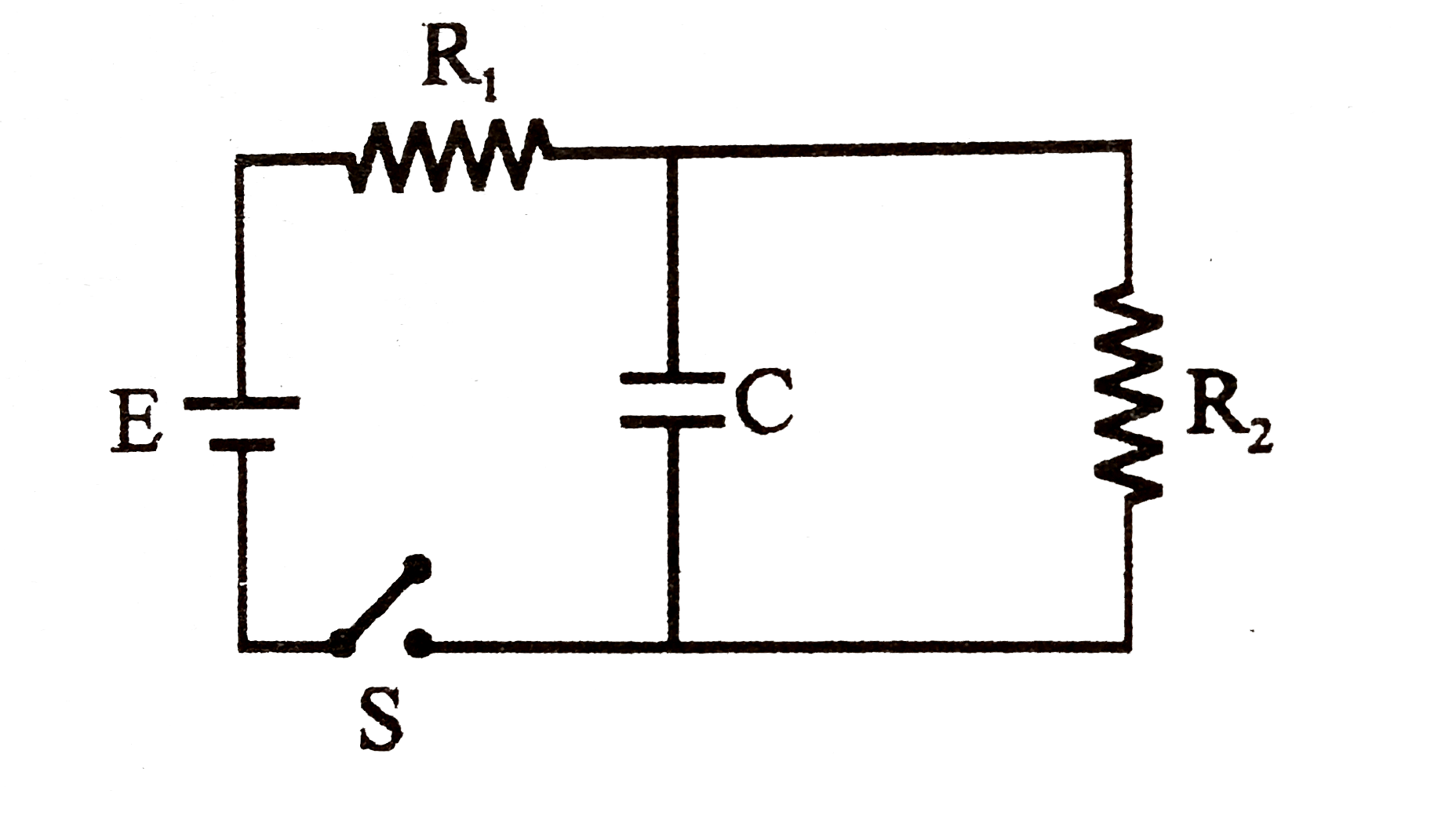
At the instant of closing the switch
View SolutionIn the circuit shown in figure switch S is closed at time t=0
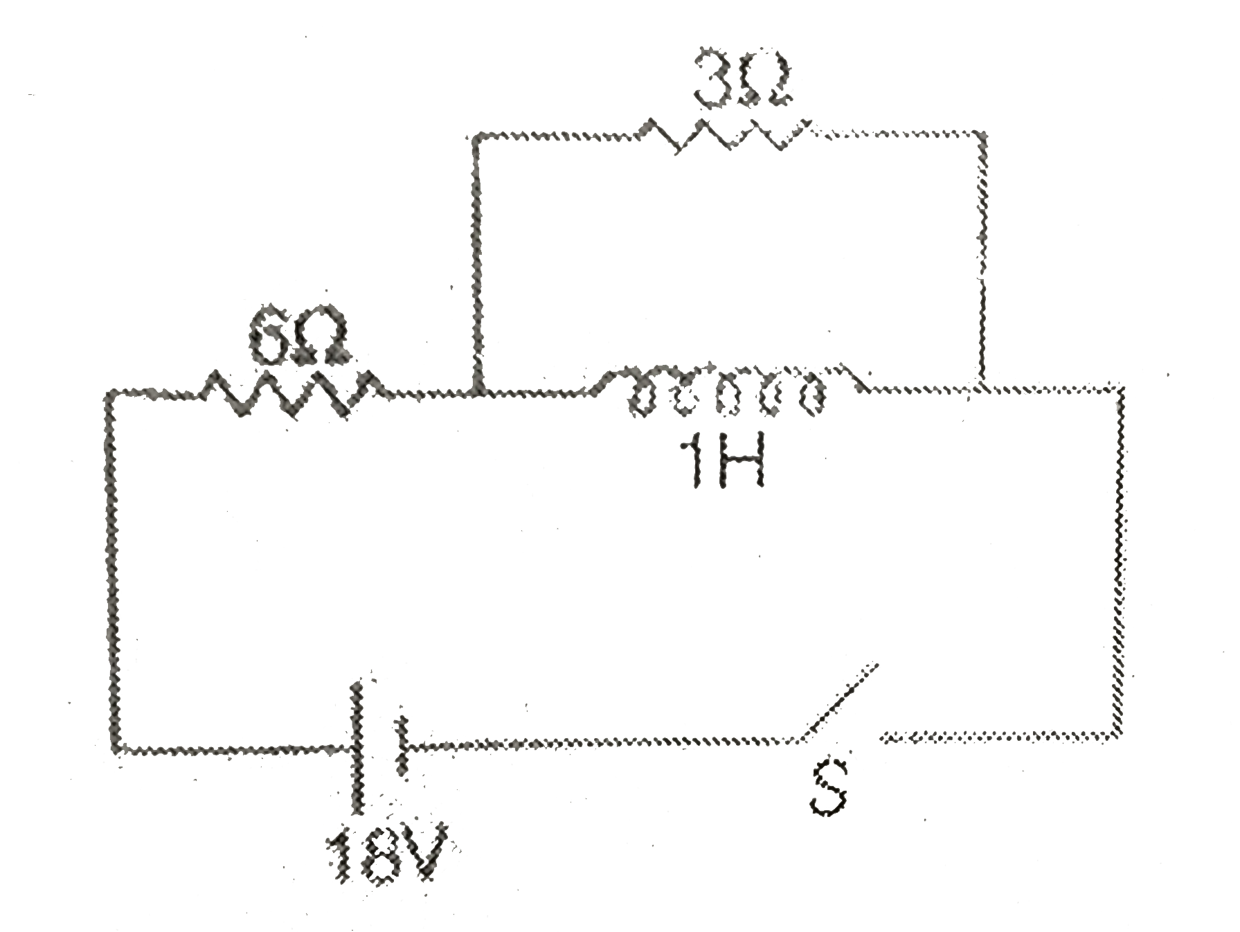
At what time current through 3Ω resistance and 1H inductor are equal?
View Solution

