Consider two circuits given below. When switches S1andS2 are closed at t=0, the charge on capacitors C1 and C2 change with time as shown in graph 1 and 2 respectively. The current i1 and i2 in the two circuits change as shown in graph 1' & 2' respectively. Write the variation of current in the second circuit as function of time after the switch is closed at t=0.e−1=0.37
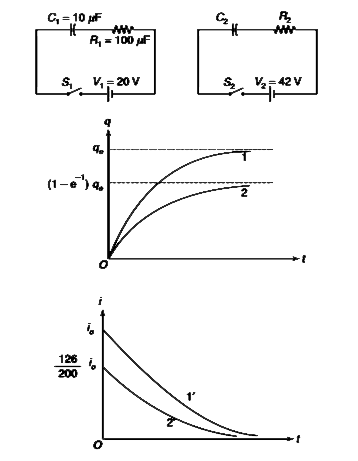
The correct Answer is:i=0.126e−1000t [t = in second]
Step by step video, text & image solution for Consider two circuits given below. When switches S_(1) and S_(2) are closed at t = 0, the charge on capacitors C_(1) and C_(2) change with time as shown in graph 1 and 2 respectively. The current i_(1) and i_(2) in the two circuits change as shown in graph 1' & 2' respectively. Write the variation of current in the second circuit as function of time after the switch is closed at t=0. e^(-1) =0.37 by Physics experts to help you in doubts & scoring excellent marks in Class 12 exams.
Updated on:21/07/2023Topper's Solved these Questions
Similar Questions
Knowledge Check
In the circuit shown in the figure, if switches S1 and S2 have been closed for a long time, then charge on the capacitor.
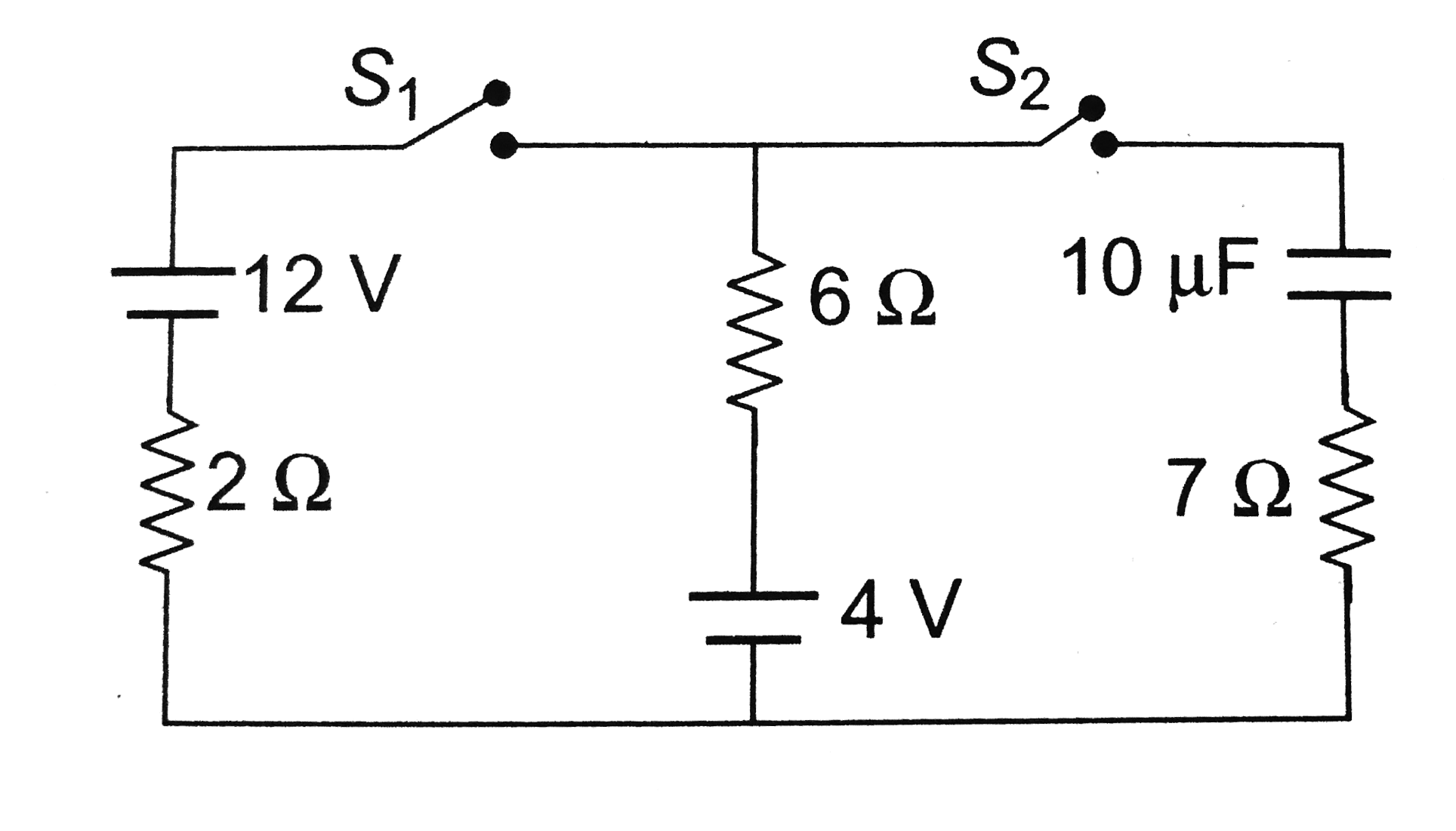 Ais 100μCBincreases to 200μC if one third of the gap of the capacitor's plates is filled with a dielectric (K=2) of same areaCboth (a) and (b) aboveDcharge on the capacitor remains unchanged if one third of the gap of the capacitor's plates is filled with a dielectric (K=2) of same area.
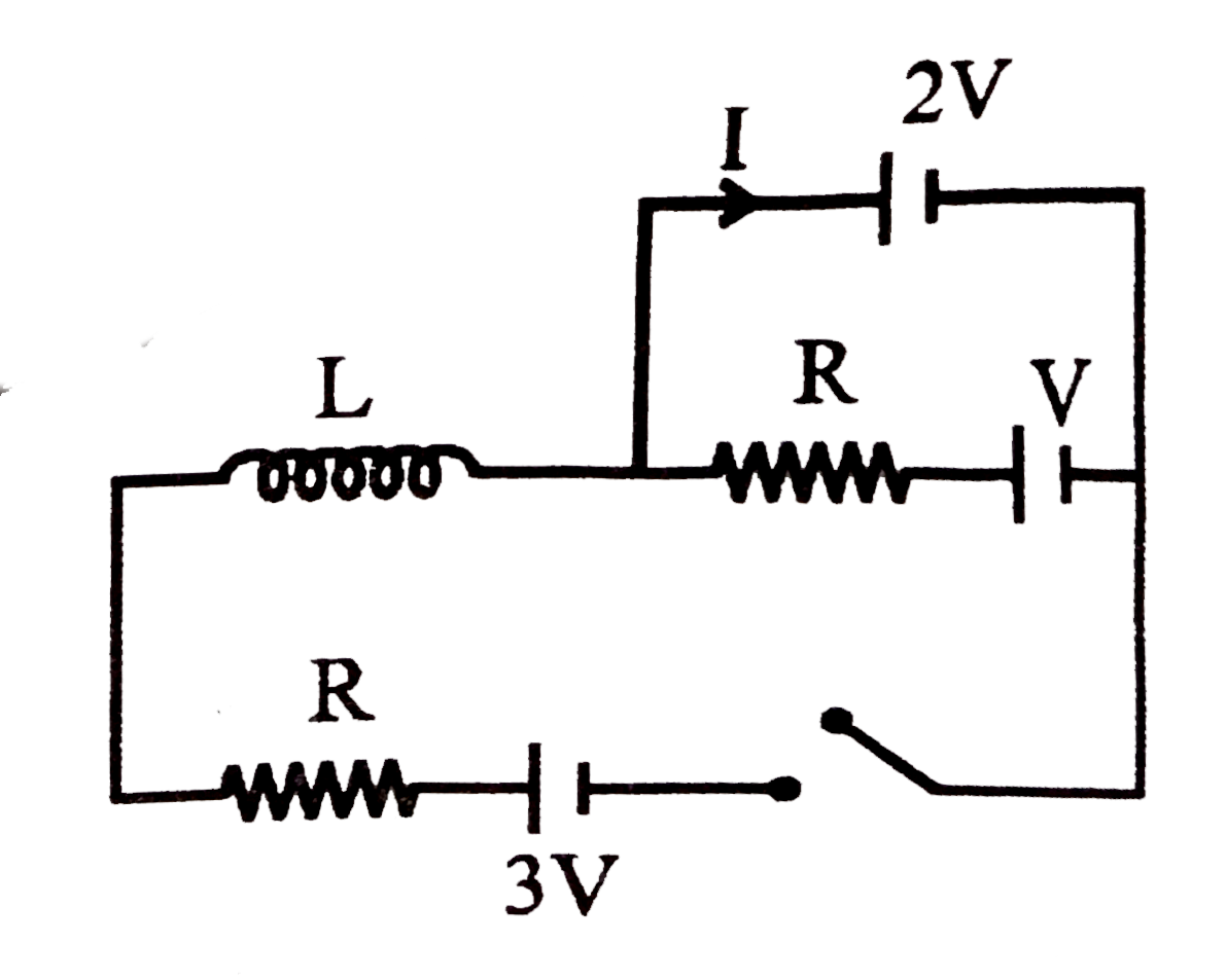
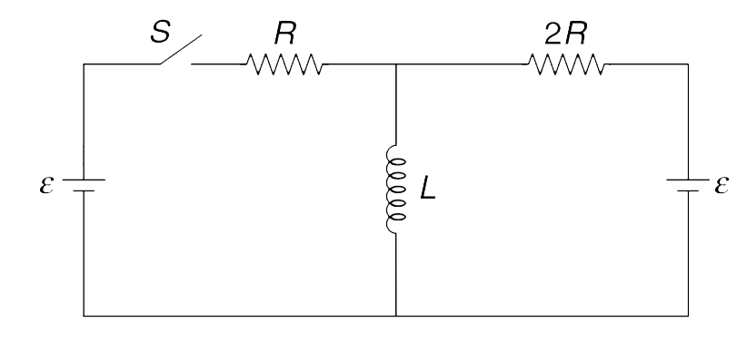
Consider the circuit shown in figure. The current through the battery a long time after the switch S is closed is:
 AER1BER2CER1+R2DE(R1+R2)(R1R2)
In the circuit shown in fig. C1=2C2 Initially, capacitor C1 is charged to a potential of V. The current in the circuit just after the switch S is closed is
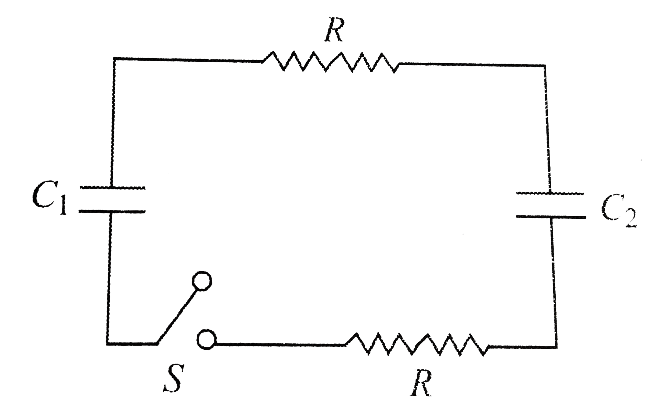 A0B2V/RC∞DV/2R
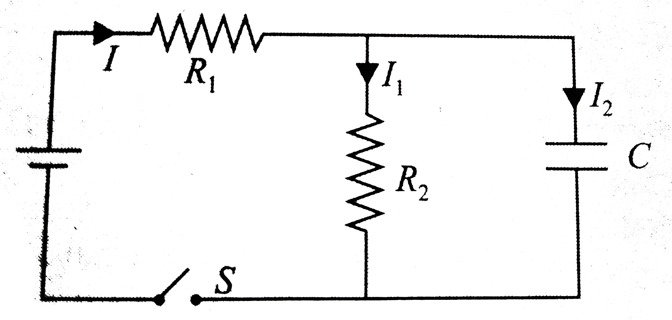
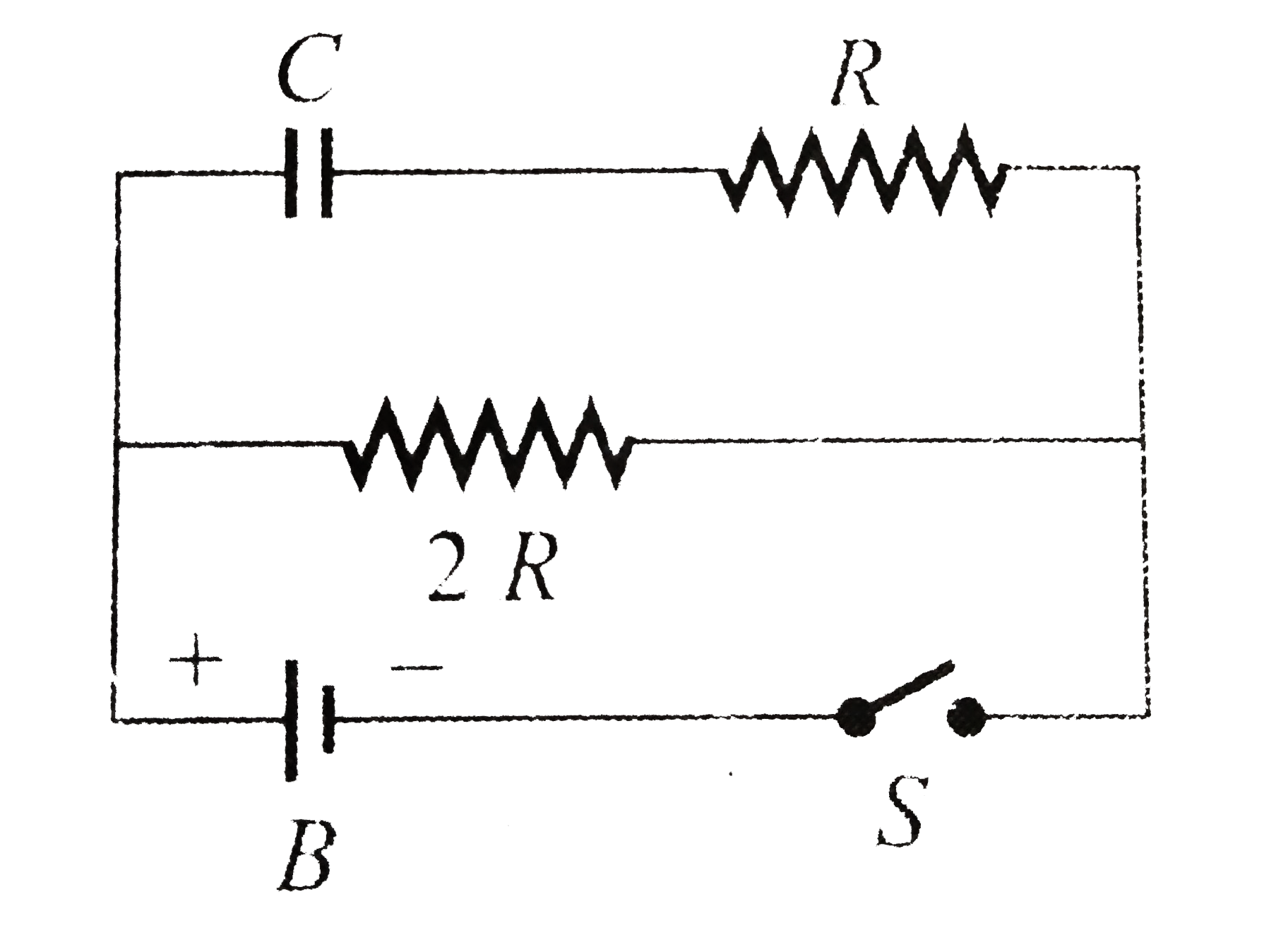
Consider the circuit shown in fig. If the switch is closed at t =0, then calculate the values of I,I1 and I2 at a. t =0 , b. =∞
View SolutionIn the circuit shown in figure C1=2C2. Capacitance C1 is charged to a potential of V. The current in the circuit just after the switch S is closed is

View SolutionCondsider
 .
.
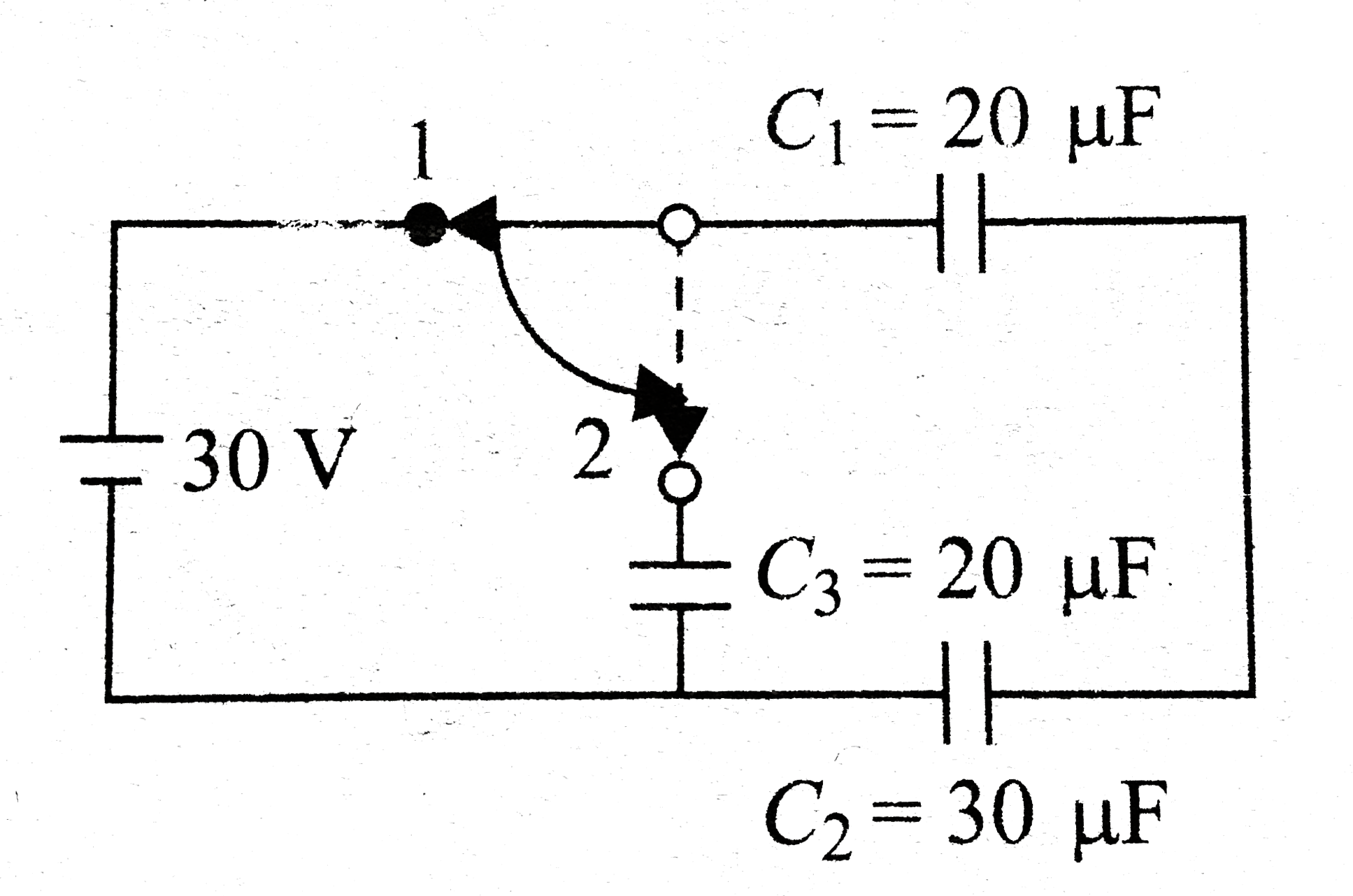
In the circuit shown is the switch can be shifted to positions 1 and 2 The charge on capacitor C1 when the switch is at position 1 is.
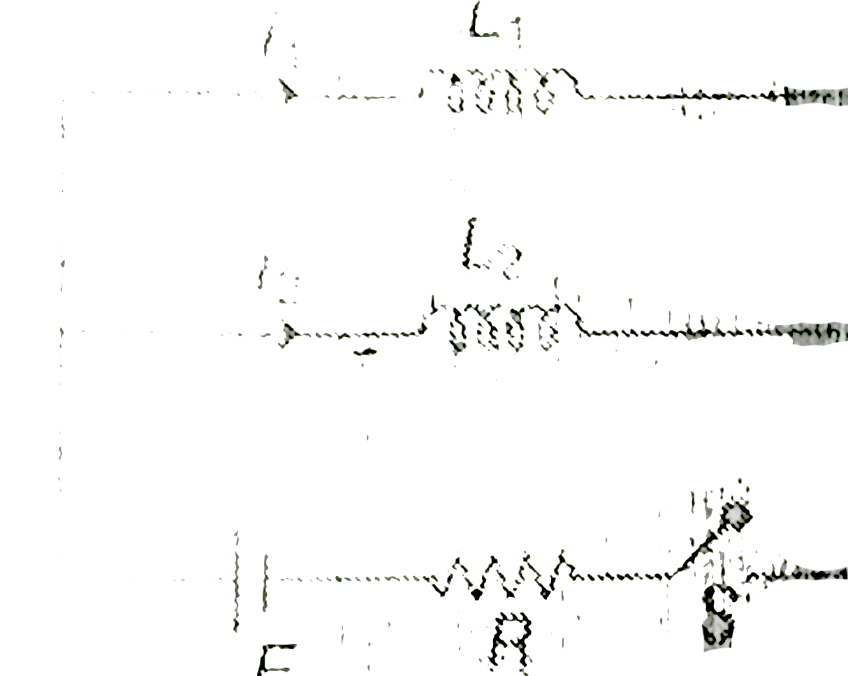
View SolutionIn the circuit shown in the figure The steady state currents i1andi2 in the coils after the switch S is closed are
View SolutionIn the circuit shown in fig, if the switch S is closed at t=0 , the capacitor charges with a time constant
View Solution

