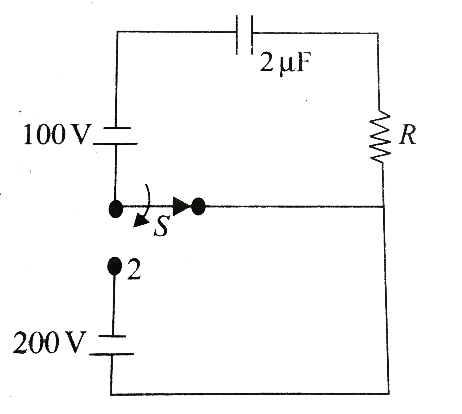
In the circuit arrangement shown in Figure, the three way switch S is kept in position 1 for a long time.
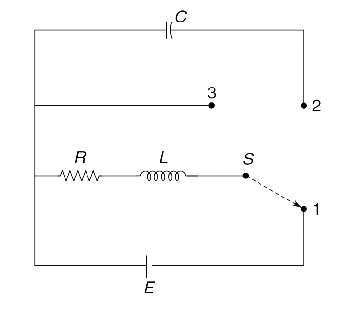
(a) Find the potential difference across the inductor immediately after the switch is thrown from posi- tion 1 to position 2.
(b) After being left in position 2 for a long time, the switch is moved to position 3. Find the potential difference across R immediately after the switch is moved to position 3. Assume no time lag in moving the switch from one position to another.
The correct Answer is:(a) E (b) zero
Step by step video, text & image solution for In the circuit arrangement shown in Figure, the three way switch S is kept in position 1 for a long time. (a) Find the potential difference across the inductor immediately after the switch is thrown from posi- tion 1 to position 2. (b) After being left in position 2 for a long time, the switch is moved to position 3. Find the potential difference across R immediately after the switch is moved to position 3. Assume no time lag in moving the switch from one position to another. by Physics experts to help you in doubts & scoring excellent marks in Class 12 exams.
Updated on:21/07/2023Topper's Solved these Questions
- ELECTROMAGNETIC INDUCTIONBook:ARIHANTChapter:ELECTROMAGNETIC INDUCTIONExercise:Level 2
Explore 39 Videos
- ELECTROMAGNETIC INDUCTIONBook:ARIHANTChapter:ELECTROMAGNETIC INDUCTIONExercise:Level 3
Explore 12 Videos
- CURRENT ELECTRICITYBook:ARIHANTChapter:CURRENT ELECTRICITYExercise:Current Electricity
Explore 105 Videos
- ELECTROSTATICSBook:ARIHANTChapter:ELECTROSTATICSExercise:Level 3
Explore 59 Videos
Similar Questions
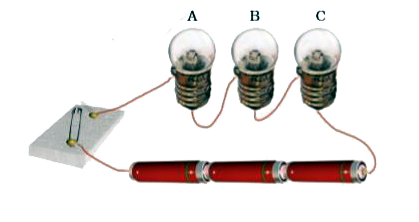
In the circuit shown in Fig. 12.3, when the switch is moved to ‘ON’ position
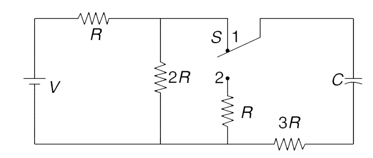
View SolutionConsider the circuit shown in the figure. The switch has been in position 1 for a long time. Answer following questions:
(a) find current through 2R.
(b) find potential difference across the capacitor.
(c) At t=0 the switch is moved to position 2. What current flows through the capacitor immediately after the switch is placed to position 2?
(d) Draw a graph of current Vs time for the current through the capacitor after the switch is moved to position 2. Indicate the time on the graph when the current becomes 37% of its value immediately after the switch is put to position 2.
View Solution
Knowledge Check
In the circuit given in fig. swithc S is at position 1 for long time. Find the total heat generated in resistor of resistance (2r0), when the switch S is shifted from position 1 to position 2.
 AC0E202BC0E20CC0E203Dnone
In the given circuit diagram figure, switch Sw is shifted from position 1 to position 2. Then
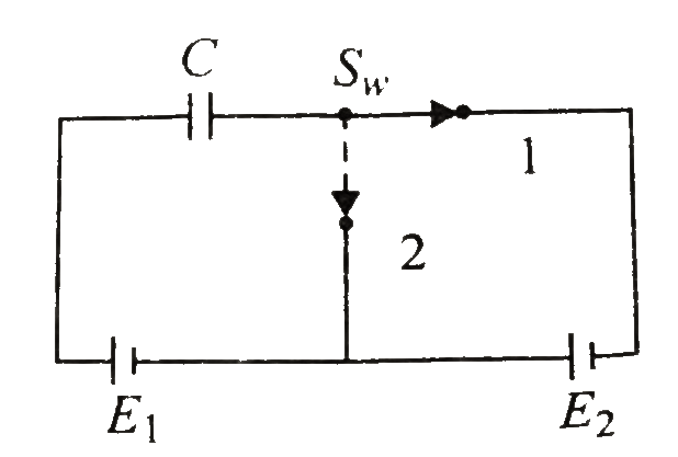 Aa charge of amount CE2 will be supplied to battery E1.Bheat generated in the circuit is CE22/2Ca charge of amount CE2 will be supplied by battery E1.Dheat generated in the circuit is CE1E2/2
In the circuit shown in fig, switch S was closed for long time. At time t-0, teh switch is opened again. The maximum potential difference across teh plates of the capacitor after the switch is opened is
 A10VB100VC20VD200V
In the circuit in Fig. switch S1 was closed for a long time . At time t=0 the switch is opened.
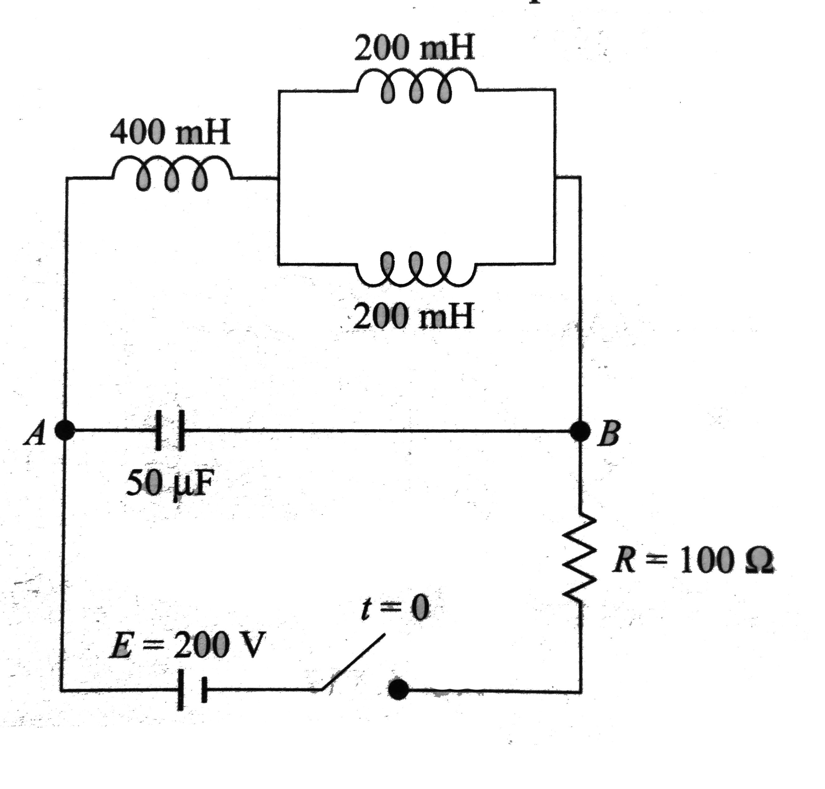
Find the maximum potentail difference across the plates of the capacitor after the switch is opened.
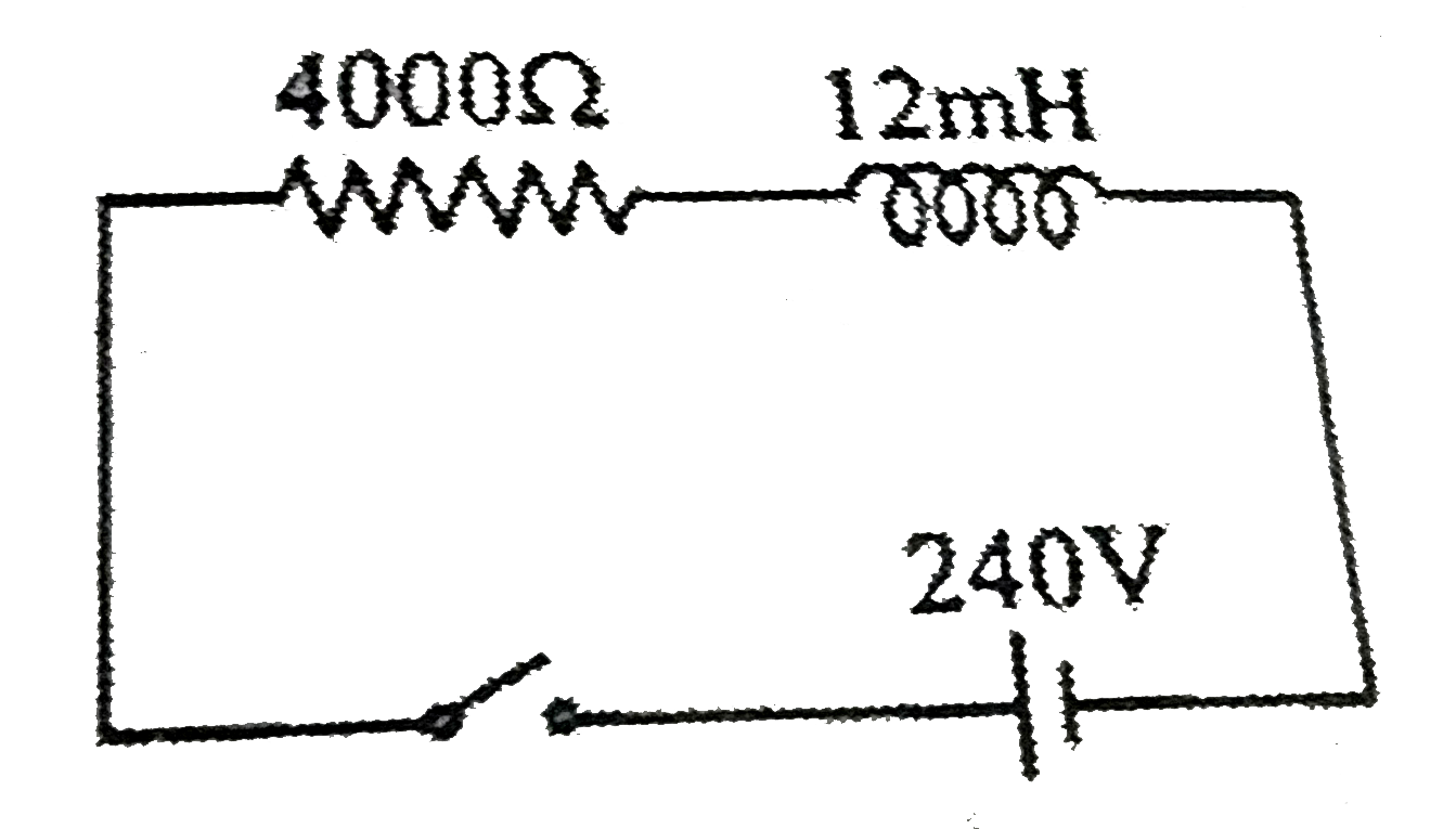
View SolutionIn the inductive circuit given in the figure, the current rises after the switch is closed. At instant when the current is 15 mA, then potential difference across the inductor will be-
View SolutionIn the circuit as shown in figure the switch is closed at t=0.
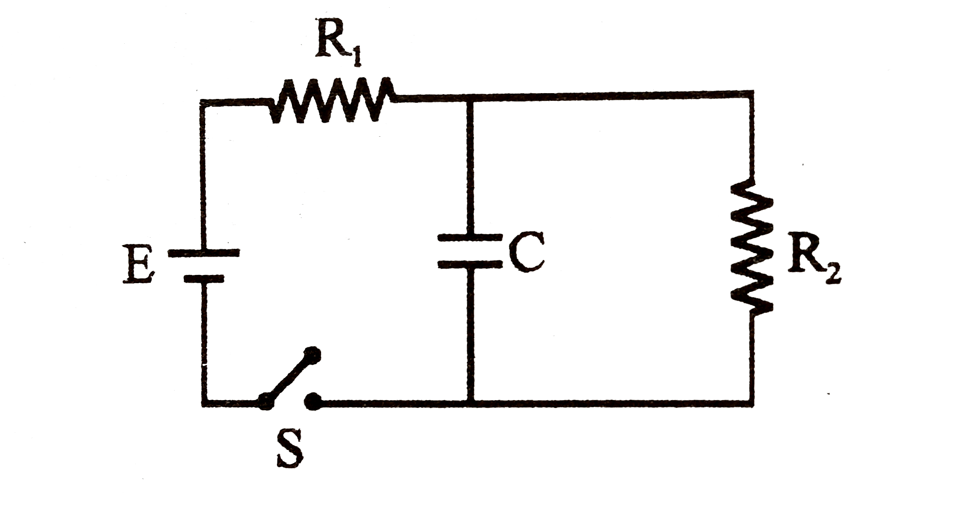
A long time after closing the switch
View SolutionIn the arrangement shown in , the switch S is find
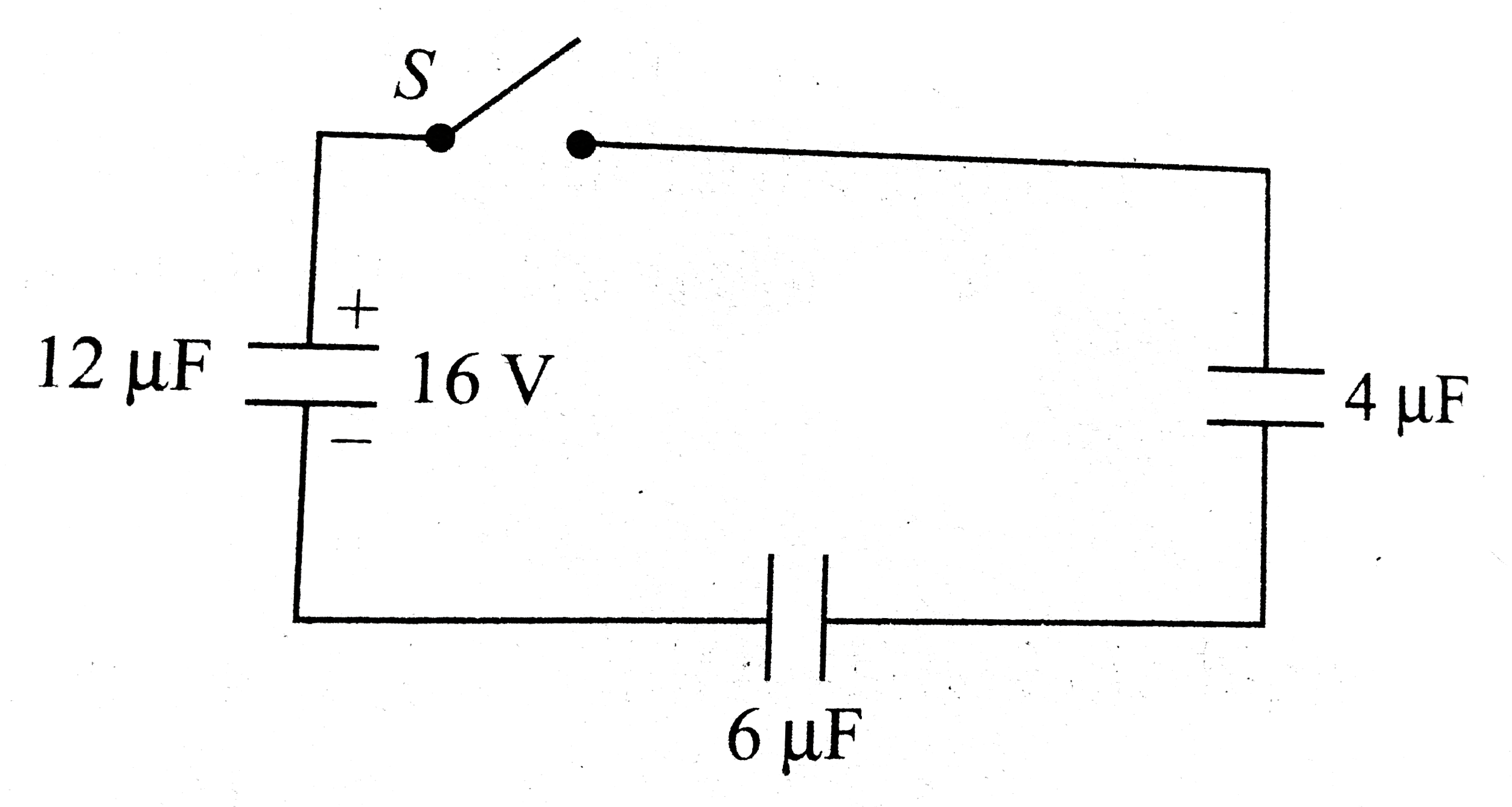 the final potential difference across the 4μF capacitor
View SolutionIn the circuit shown in the figure, the switch S is in position 1 for a long time. Now the switch is thrown to position 2. Find the total heat developed in the circuit till the steady state is reached again.
View Solution

