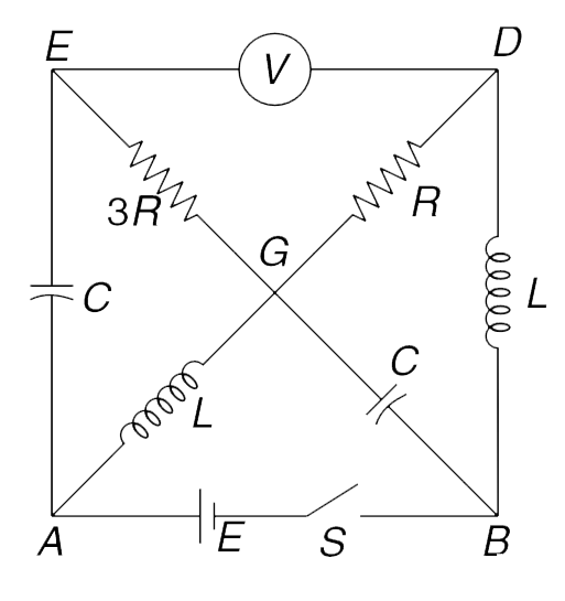
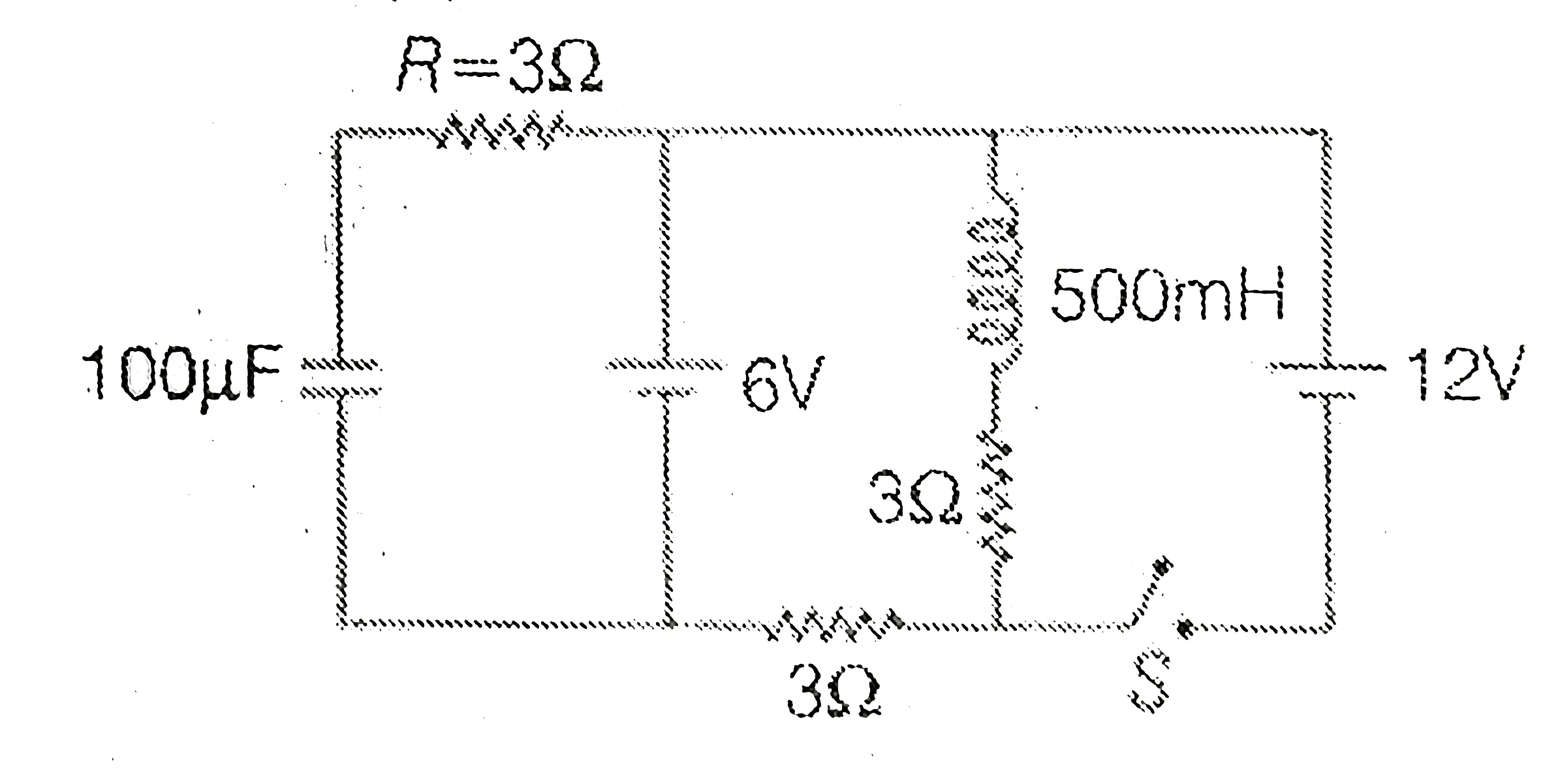
In the circuit shown, switch S is kept closed and the circuit is in steady state.
(a) Find reading of the ideal voltmeter
(b) Now the switch is opened. Find the reading of the voltmeter immedi- ately after the switch is opened.
(c) Fid the heat dissipated in resistance R after the switch is opened.
The correct Answer is:(a) E
(b) 2E with polarity reversed
(c) 12E2(LR2+C)
Step by step video, text & image solution for In the circuit shown, switch S is kept closed and the circuit is in steady state. (a) Find reading of the ideal voltmeter (b) Now the switch is opened. Find the reading of the voltmeter immedi- ately after the switch is opened. (c) Fid the heat dissipated in resistance R after the switch is opened. by Physics experts to help you in doubts & scoring excellent marks in Class 12 exams.
Updated on:21/07/2023Topper's Solved these Questions
Similar Questions
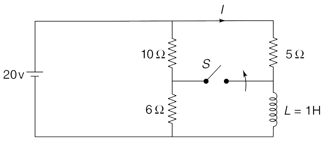
In the circuit shown, the switch ‘S’ has been closed for a long time and then opens at t = 0.
(a) Find the current through the inductor just before the switch is opened.
(b) Find the current I a long time after the switch is opened.
(c) Find current I as a function of time after the switch is opened. Also write the current through the cell as a function of time.
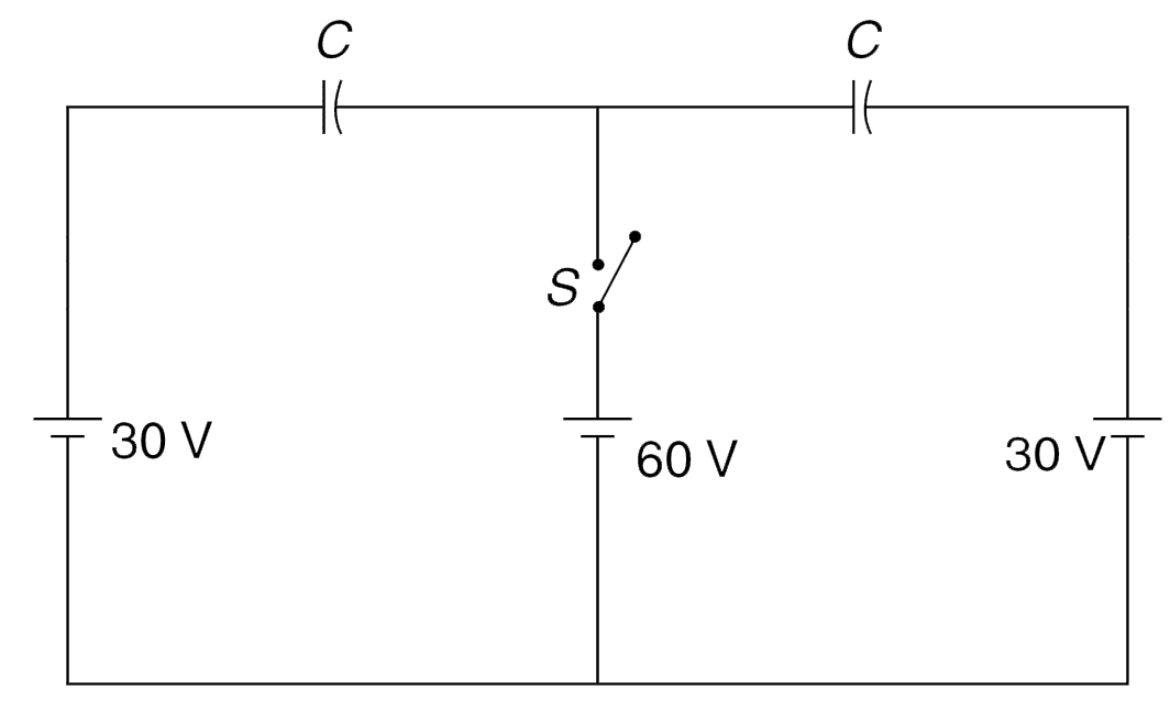
View SolutionFind heat dissipated in the circuit after switch S in closed. C=2μF.
View Solution
Knowledge Check
In the circuit diagram the current through the battery immediately after the switch S is closed is
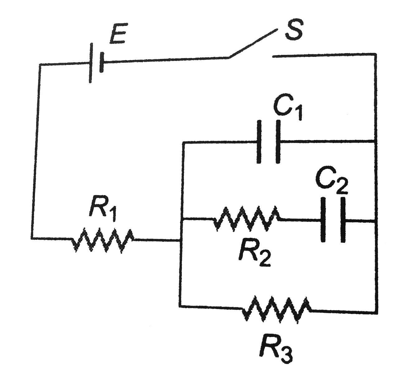 AzeroBER1CER1+R2DER1+R2R3R2+R3
In the circuit shown in figure, switch S is initially closed and S is open. Find V-V
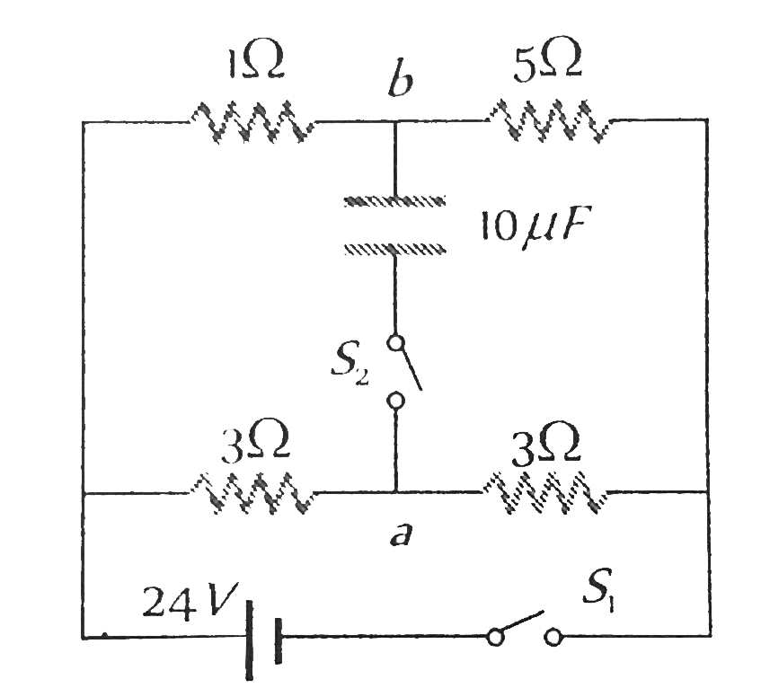 A4VB8VC12VD16V
In the circuit P≠R, the reading of the galvanometer is same with switch S open or closed. Then
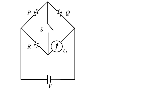 AIR=lGBIp=lGClQ=lGDIR=IQ
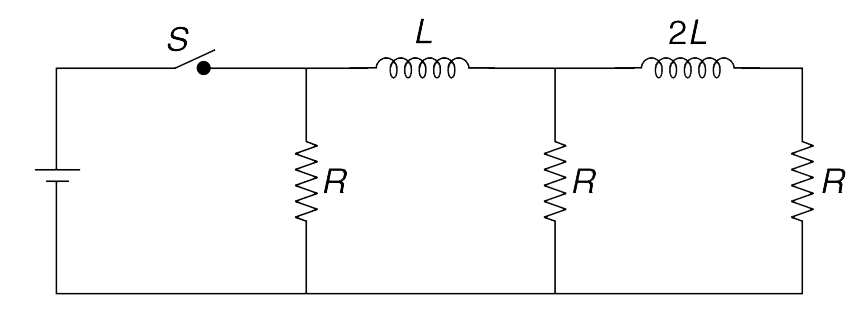
In the circuit shown in figure, the current through each resistor is I. Find the currents through the resistors immediately after the switch ‘S’ is opened. How much heat will get dissipated in the circuit after thw switch is opened ?
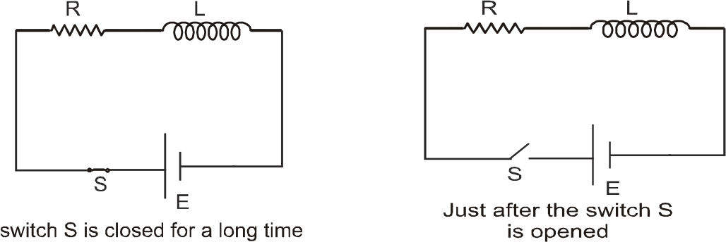
View SolutionIn the LR circuit the switch S was closed for a long time. The ideal cell in the circuit has emf E volts.Later on the switch is opened. The current in the resistor of resistance R ohms just after the switch was opened is XE4R, then x is
View SolutionIn the circuit shown as P≠R and the reading of the galvanometer G is same with the switch open or closer. Then
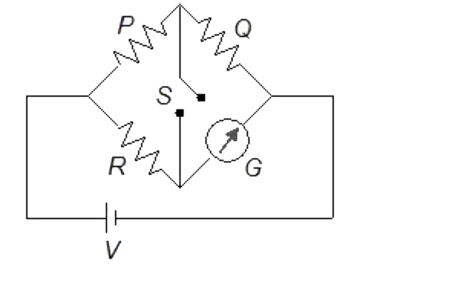
View SolutionIn the circuit P≠R, the reading of the galvanometer is same with switch S open or closed. Then

View SolutionIn the circuit diagram shown in figure, initially switch S is opened and the circuit is in steady state. At time t=0, the switch S is closed and the new steady state is reached after some time. Choose the correct option(s)
View Solution

