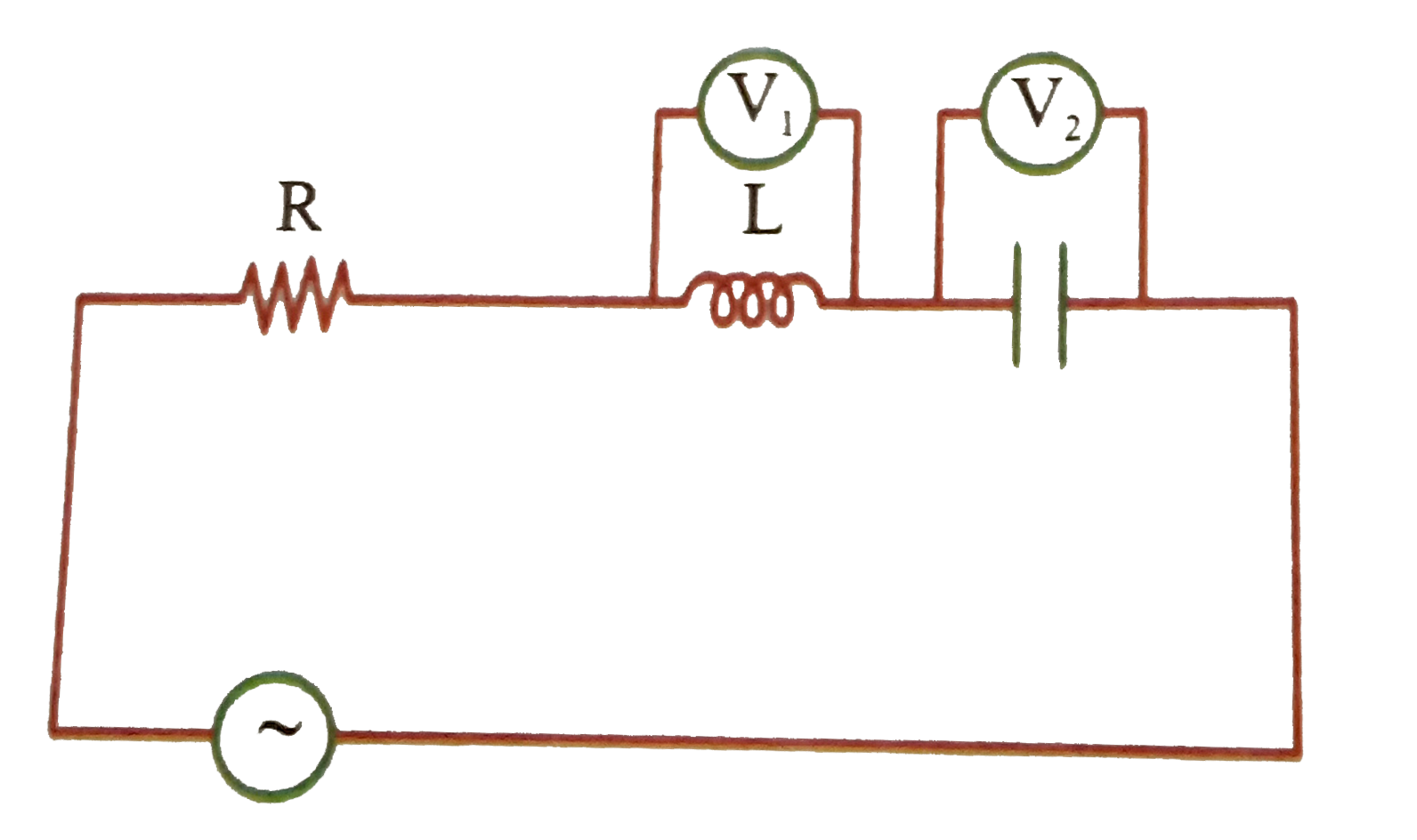
In the figure shown R=100ΩL=2πH and C=8πμF are connected in series with a.c source of 200 volt and frequency 'f'. V1 and V2 are two hot-wire voltmeters. If the readings of V1 and V2 are same then:
f=125Hz,v1v2=1
f=250πHz,v1v2=1
current through R is 1A, v1v2=1
current through R is 2A,v1v2=2
The correct Answer is:A
V1=V2⇒xL=xc
⇒f=12π√LC=125Hz
I0=v0R=200100(∵X=0∴Z=R)
=2A
V1=V2=IXL=I.(ωL)=2×2π×125×2/π
=100 volt
=1000 volt
Topper's Solved these Questions
Similar Questions
A resistor of 50 ohm, an inductor of (20/π) H and a capacitor of (5/π)μF are connected in series to an a.c. source 230 V, 50 Hz. Find the current in the circuit.
View SolutionA 2 uF capacitor, 100 Ω resistor and 8 H inductor are connected in series with an a.c. source. Find the frequency of the a.c. source for which the current drawn in the circuit is maximum. If the peak value of emf of the source is 200 V, calculate the
(i) maximum current, and (ii) inductive and capacitive reactance of the circuit at resonance.
View Solution
Knowledge Check
In the figure shows R=100Ω,L=2πH and C=8πμF are connected in series with an a.c. source of 200 volt and frequency f. V1 and V2 are two hot-wire voltmeters. If the reading of V1 and V2 are same, then
 Af=125HzBf=250πHzCCurrent through R is 2ADV1=V2=1000 volt
In an LCR series ac circuit the voltage across L,C and R are V1,V2 and V3 respectively The voltage of the source is .
A√(V1−V2)2+V23B√V21+(V2−V23C√V22+(V1−V3)2DV1+V2+V3In the circuit shown, L=1μH,C=1μF and R=1kΩ. They are connected in series with an a.c. source V=V0sinωt as shown. Which of the following options is/are correct?
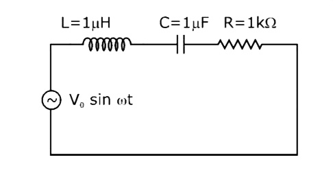 AThe current will be in phase with the voltage if ω=104rad.s–1BAt ω>>106rad.s–1, the circuit behaves like a capacitorCThe frequency at which the current will be in phase with the voltage is independent of RDAt ω≅0 the current flowing through the circuit becomes nearly zero.
A 100 mH inductor, a 25μF capacitor and 15Ω resistoer are connected in series to a 120 V, 50Hz a.c source. Calculate the resonant frequency .
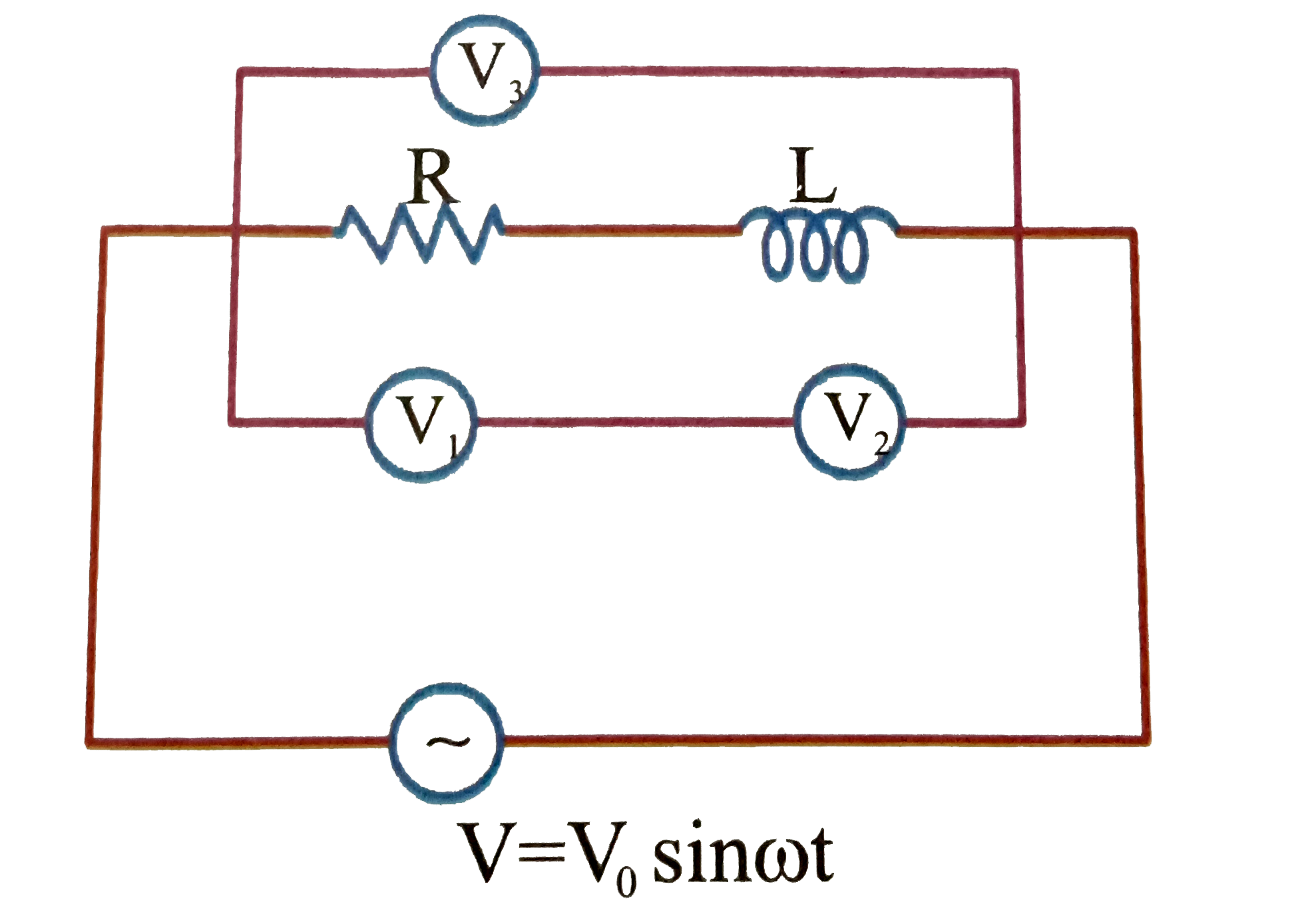
View SolutionA resistance & ideal inductor is connected in the A.C circuit. Here V1,V2&V3 are the reading of three hotwire ideal voltmeter
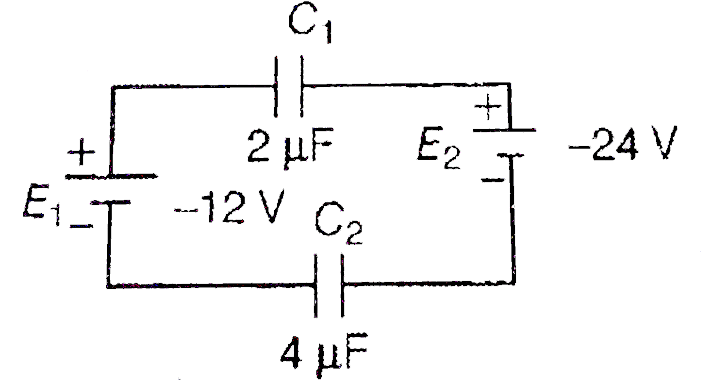
View SolutionTwo capacitors C1 and C2 are connected in a circuit as shown in figure. The potential difference (VA−VB) is
View SolutionThe diagram shows a capacitor C and a resistor R connected in series to an AC source. V1 and V2 are voltmeters and A is ammeter
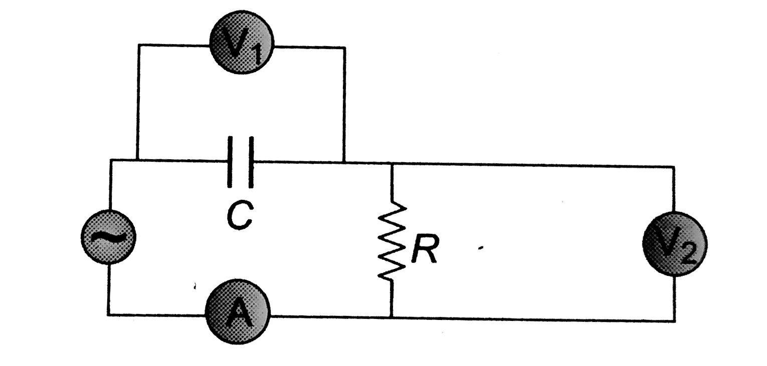
Now, consider the following statements :
(I) Reading in A and V2 are always in phase.
(II) Reading in V1 is ahead in phase with reading in V2,
(III) Reading in A and V1 are always in phase. Which of these statements are/is correct
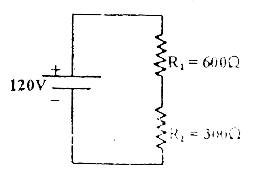
View SolutionA voltmeter of resistance 600Ω when connected in turn across resistances R1 and R2 gives readings of V1 and V2, respectively. If the battery is ideal, then
View Solution

