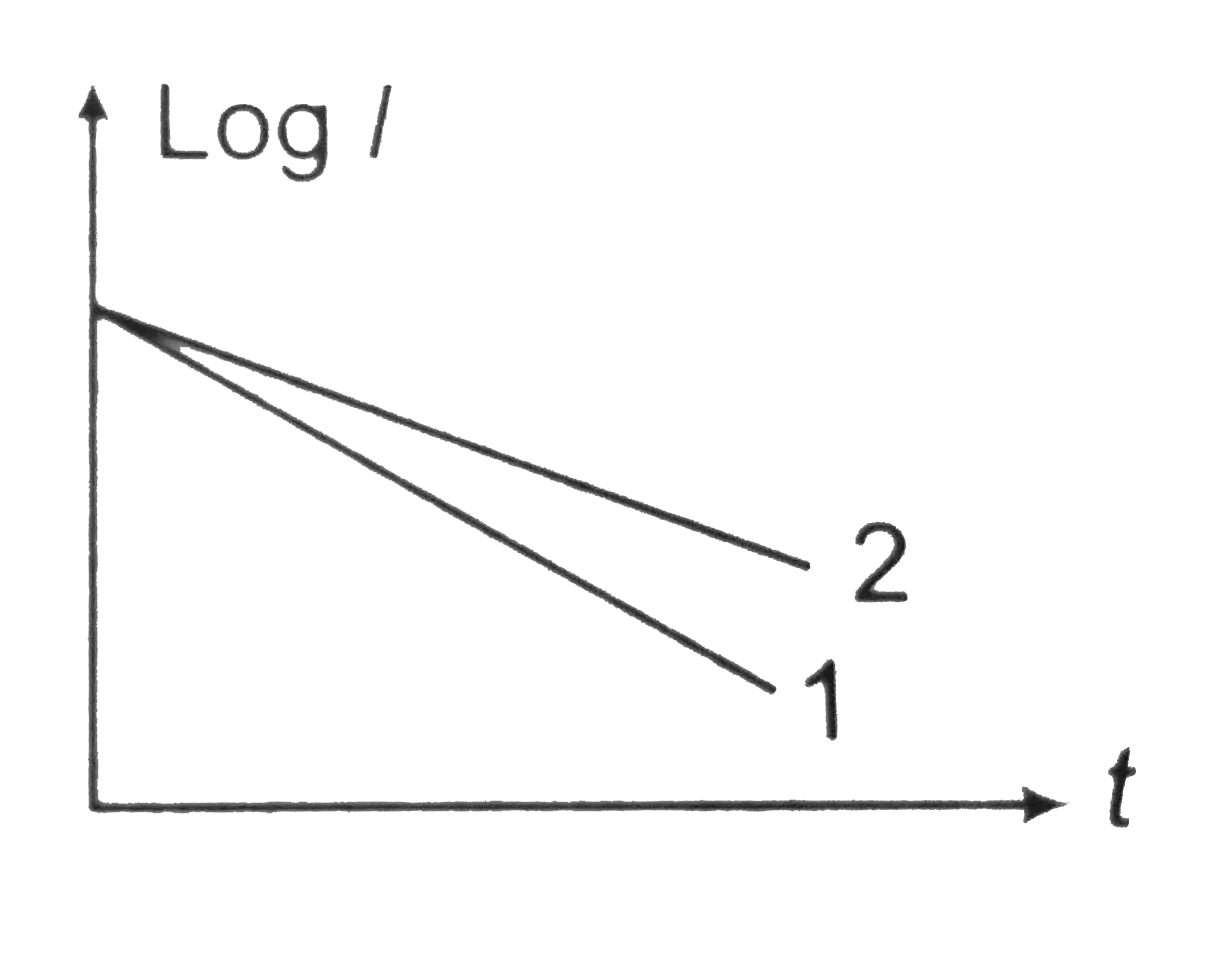
A graph between current and time during charging of a capacitor by a battery in series with a resistor is shown. The graphs are drawn for two circutis. R1,R2,C1,C2 and V1,V2 are the values of resistance, capacitance and EMF of the cell in the two circuits. If only two parameters (out of resistance, capacitance, EMF) are different in the two circuits. What may be the correct options (s) ?
V1=V2,R1>R2,C1>C2
V1>V2,R1>R2,C1=C2
V1<V2,R1<R2,C1=C2
V1<V2,C1>C2,R1=R2
The correct Answer is:C
I=I0etRC
logI=logI0−tRC⇒logI=log(V0R)−tRC
from above equation only option (3) is correct.
Topper's Solved these Questions
Similar Questions
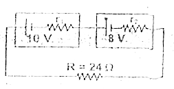
Two cells having emf's of 10 V and 8 V, respectively, are connected in series with a resistance of 24Ω In the external circuit. Their internal resistances are 2Ω/V (proportional to their emf's). Find the current in the circuit
 View Solution
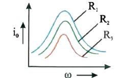
The graph between current and frequency for LCR series circuit is drawn for three different resistor R1,R2 & R3 . Which one is correct regarding resistance.
 View Solution
Knowledge Check
- Question 1 - Select One
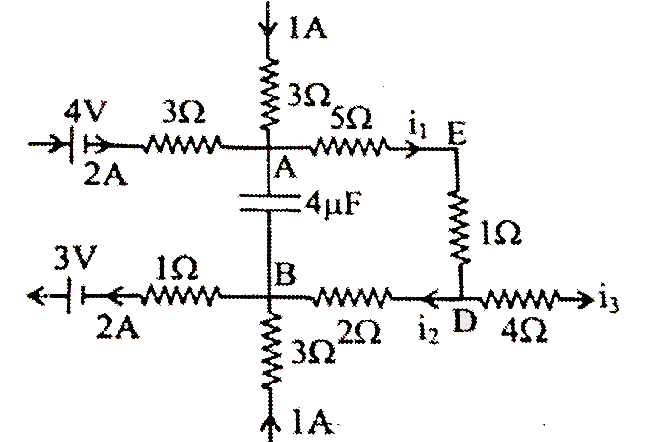
The figure shows a part of the circuit in the steady state. The currents, the valuces of resistances and emfs of the cells are shown in the figure. The circuit also contains a capacitor of capacitance C=μF. The value of i1 is-
 A1AB2AC3AD4A
 - Question 2 - Select One or More
A capacitor of capacitance C1 is charged to a potential difference V and then connected with an uncharged capacitor of capacitance C2 a resistance R. The switch is closed at t = 0. Choose the correct option(s):
AThe initial current through the resistance is VRBThe current through the resistance as a function of time is i(t)=VRe−tτ where τ=R(C1C2C1+C2)CThe charge on capacitor C1 as a function of time is q1(t)=(C1VC1+C2)(C1+C2e−tτ)DAfter a long time, the potential difference across the capacitor C1is(C1C1+C2)V - Question 3 - Select One or More
Resistor of resistance R and a capacitor of capacitance Care connected in series to a battery of emf E, through a switch and this circuit is called A. Similarly, inductor of inductance L and resistor of resistance R are connected in series to a battery of emf Ethrough a switch and this circuit is called B. Switches in both the circuits A and B are closed at t= 0.
ACurrent in circuit A is E/R just after t = 0BCharge on capacitor long after t = 0 is CECCurrent in circuit B is just after t = 0DCurrent through inductor long after t = 0 is E/R
A battery of emf 2 V and internal resistance r is connected in series with a resistor of 10Ω through an ammeter of resistance 2Ω. The ammeter reads 50 mA. Draw the circuit diagram and calculate the value of r.
View SolutionThe charge across the capacitor in two different RC circuit 1 and 2 are potted as shown in figure.
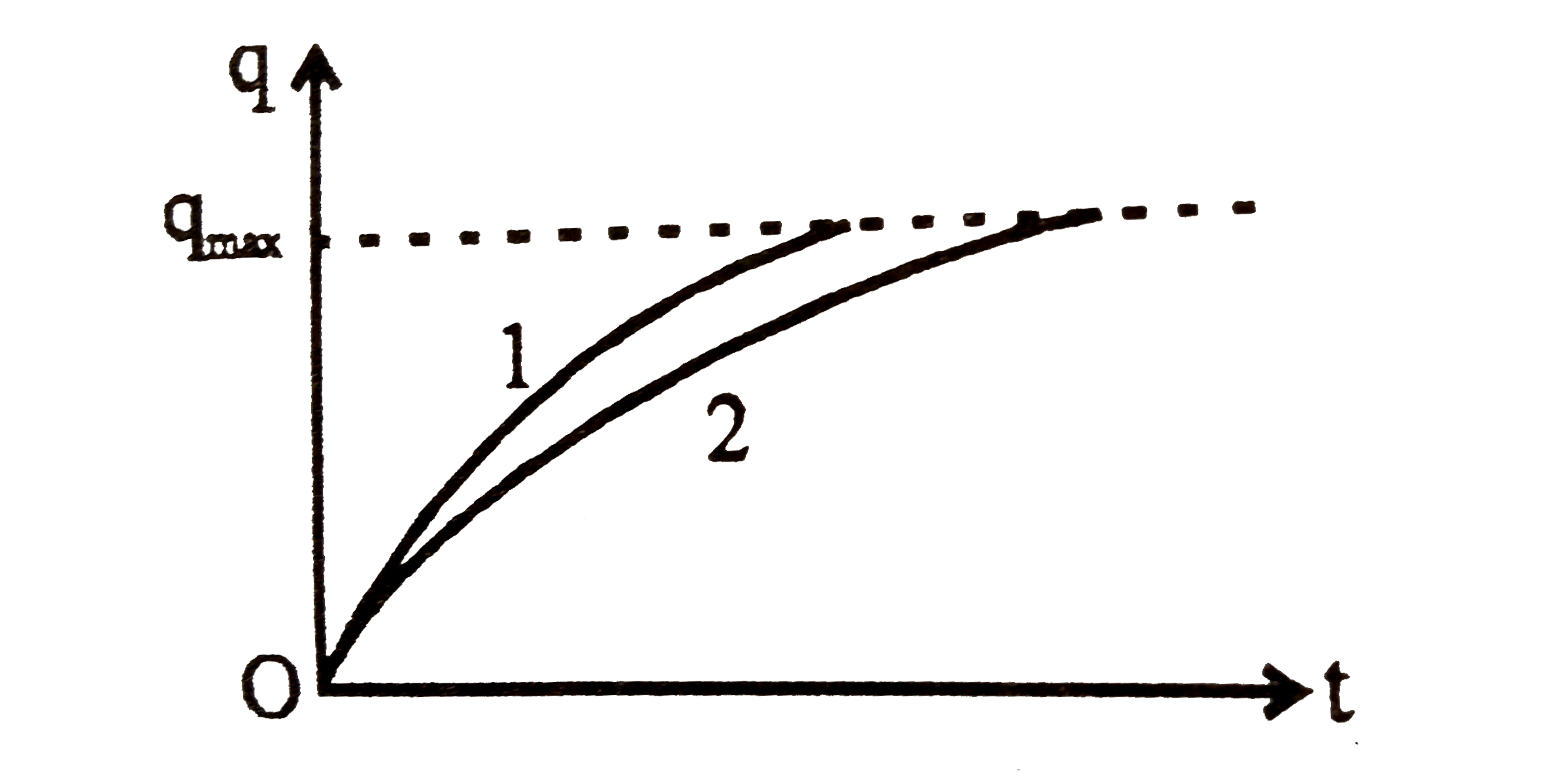
Identify the correct statement (s) related to the R1,R2,C1 and C2 of the two RC circuit-View SolutionA battery of emf 15 V and internal resistance of 4Ω is connected to a resistor. If the current in the circuit is 2A and the circuit is closed. Resistance of the resistor and terminal voltage of the battery will be
View Solution
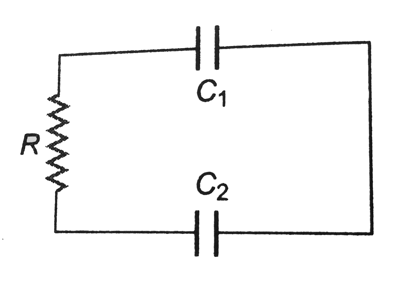
Two cells of emf 4 V and 8 V are connected to two resistor 4Ω and 6Ω as shown. If 8 V cell is short circuited. Then current through resistance 4Ω and 6ΩView SolutionA capacitors C1 is charged to a potential V and connected to another capacitor in seris with a resistor R as shown. It is observed that heat H1 is dissipated across resistance R, tilll the circuit reaches steady state. Same process is repeated using resistance of 2R. If H2 is heat dissipated in this case then
 View Solution

