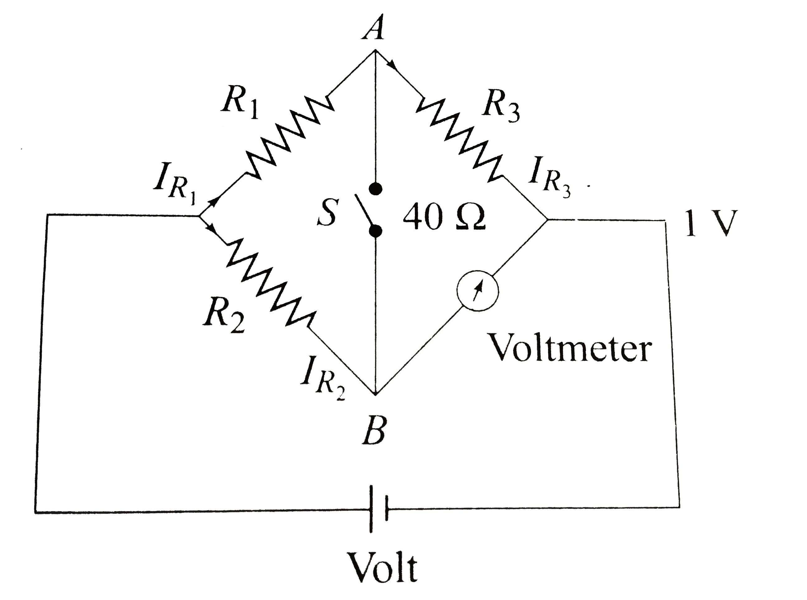
The switch in Figure (a) closes when Vc=2V/3 and opens when Vc=V/3. The voltmeter reads a voltage as plotted in figure (b). What is the period T of the waveform? (take R1=6R and R2=3R, and ln2=0.7 if required)
(a) 
12RC
8.4RC
11RC
none of these
The correct Answer is:B
When the switch closes at Vc=2V/3 the capacitor discharges through R2=3R
T (discharge) =3RCln2 (since the voltage halves).
The charging occurs through R1+R2=9R
T (charge) =9RCln2
T=12RCln2≈8.4RC
Topper's Solved these Questions
- TEST PAPERSBook:FIITJEEChapter:TEST PAPERSExercise:PHYSICS
Explore 747 Videos
- SIMPLE HARMONIC MOTIONBook:FIITJEEChapter:SIMPLE HARMONIC MOTIONExercise:Assignment Problems (Objective) (Level-II)
Explore 20 Videos
- WORK, ENERGY AND POWER Book:FIITJEEChapter:WORK, ENERGY AND POWER Exercise:COMPREHENSIONS ( Comprehension-II)
Explore 5 Videos
Similar Questions
Two spheres of radii R and 2R are charged to potential V0 and 2V0 and are connected by a battery of emf V0 as shown in figure. When switch 'S' is closed then
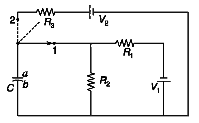
View SolutionIn the circuit shown in fig. the switch is kept closed in position 1 for a long time. At time t=0 the switch is moved to position 2. Write the dependence of voltage (VC) across the capacitor as a function of time (t). Take VC to be positive when plate a is positive.
Given: R1=20Ω,R2=60Ω,R3=400kΩ,V1=40V,V2=90VandC=0.5μF.
View Solution
Knowledge Check
VC is the ideal voltmeter in the figure. Resistance of the resistor shown is R. Initially the switch is in position 2 when charging of the capacitor starts. Initially the capacitor was uncharged. The switch in circuit shifts automatically from 2 to 1 when VC>2V/3 and goes back to 2 from 1 when VC<V/3. The ideal voltmeter reads voltage across capacitor as plotted. What is the period T of the wave from in terms of R and C ?
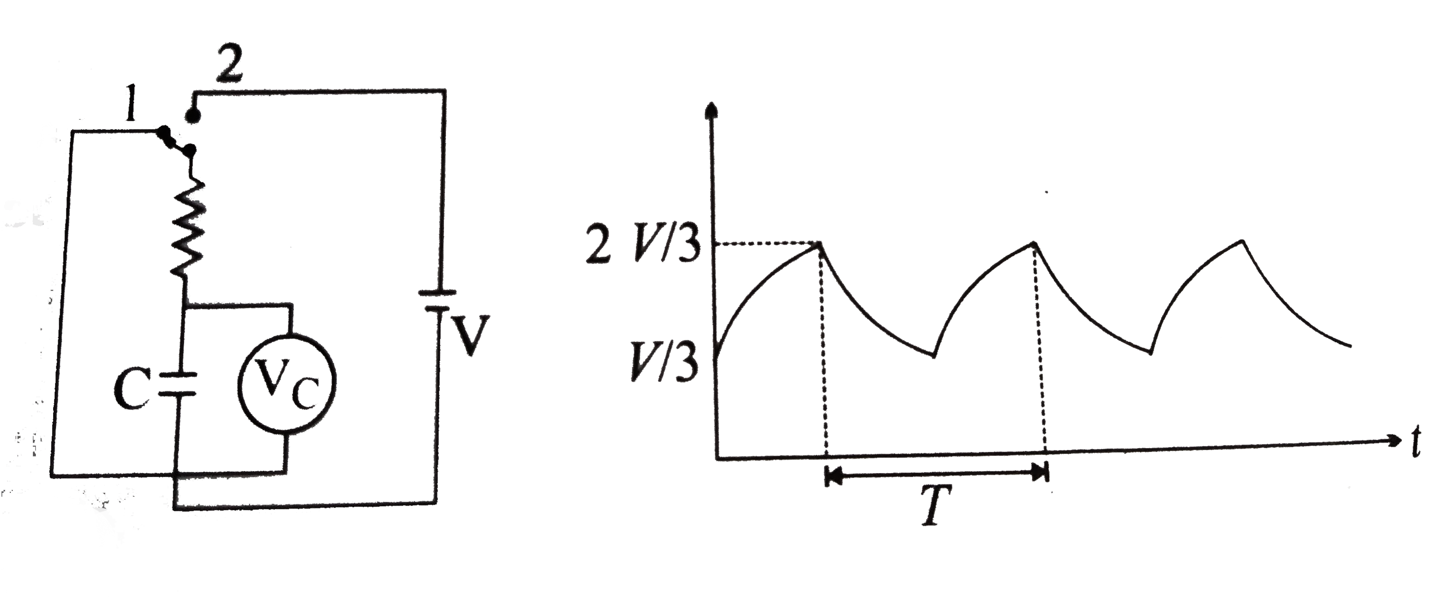 ,A3RC1n3B2RC1n2C(RC/2)1n2Dnone of these
In the following figure, the reading of an ideal voltmeter V is zero. Then, the relation between R, r1 and r2 is
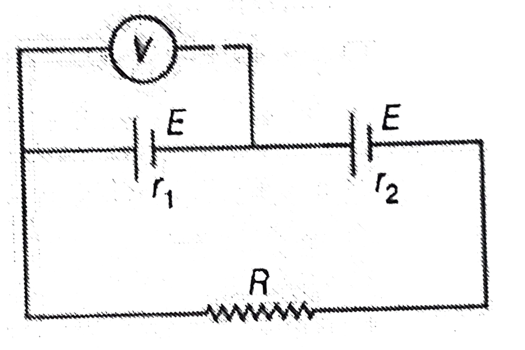 AR=r2−r1BR=r1−r2CR=r1+r2DR=r1r2r1+r2
An ammeter A, a voltmeter V and a resistance R are connected as shown in the figure. If the voltmeter reading is 1.6V and the ammeter reading is 0.4A, then R is
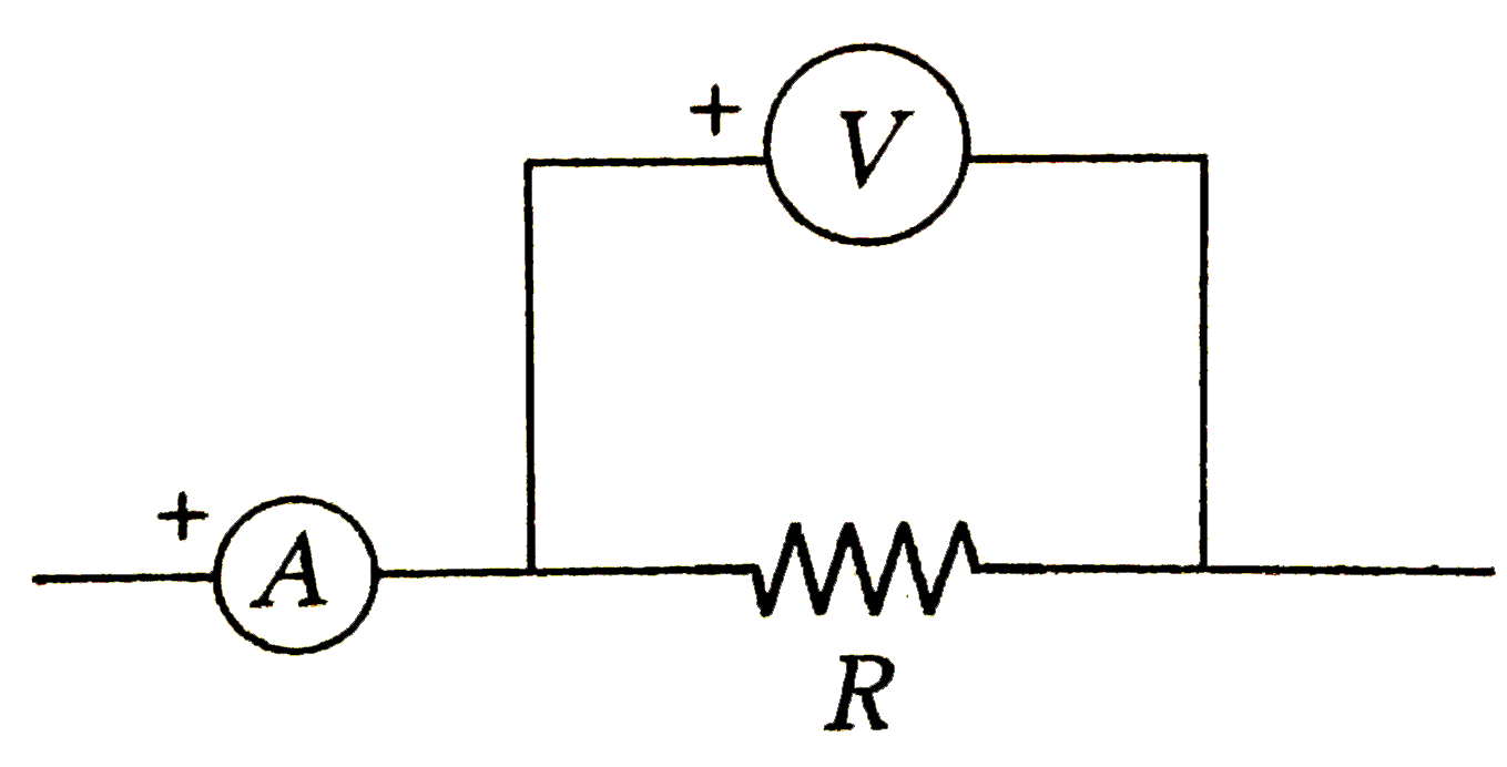 Aequal to 4ΩBgreater than 4ΩCless than 4ΩDbetween3Omegaand4Omega
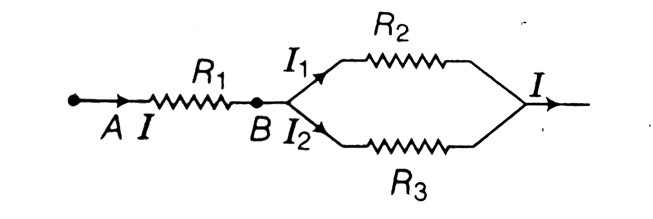
The circuit in figure, where there are three resistors R1,R2 and R3 . If the voltage between A and C is V, the current / is given by
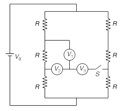
View SolutionIn the circuit shown in figure all resistances are identical (each equal to R) and the cell has an emf of V0. The three voltmeters V1,V2andV3 are identical and are nearly ideal.
(a) find the reading of the voltmeter V1 when switch ‘S’ is open.
(b) find the reading of the voltmeter V1 after the switch is closed
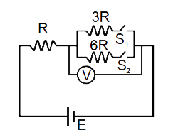
View SolutionIn the circuit shown in figure reading of voltmeter is V1 when only S1 is closed , reading of voltmeter is V2 when only S2 is closed . The reading of voltmeter is V3 when both S1 and S2 are closed then
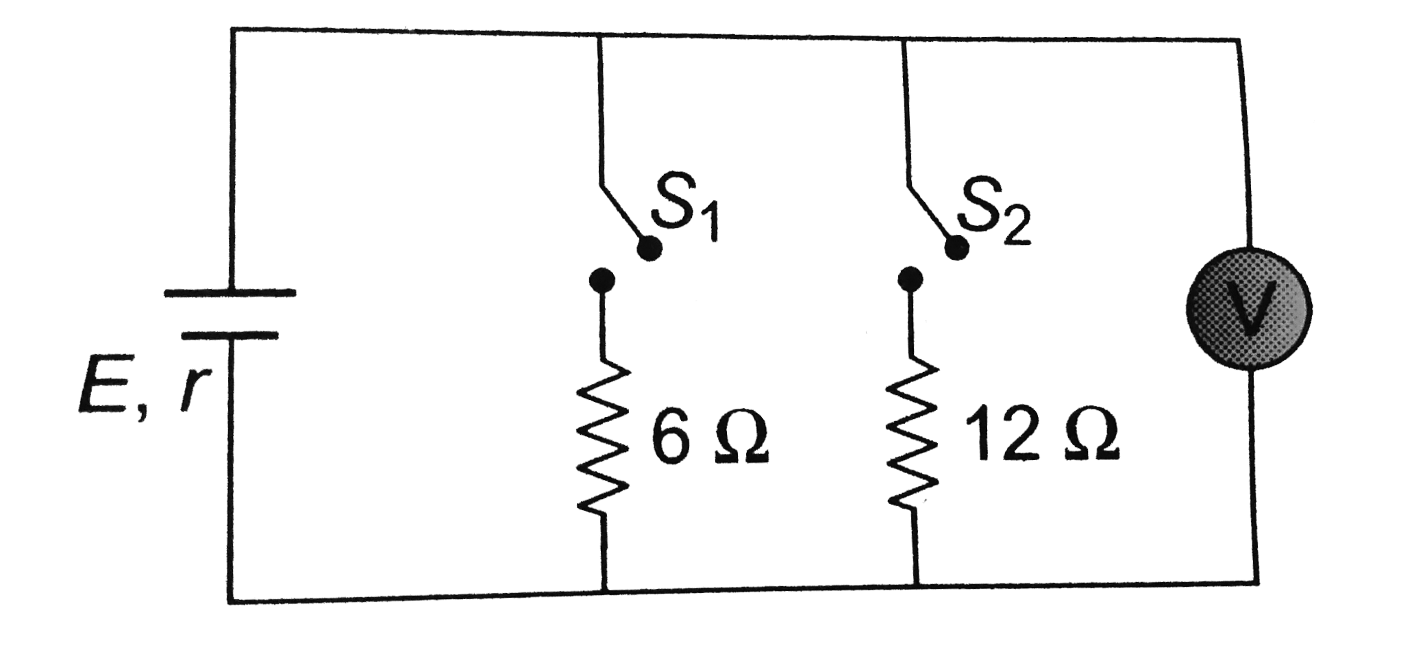
View SolutionIn the circuit shown, when switch S1 is closed and S2 is open, the ideal voltmeter shows a reaiding of 18V. When switch S2 is closed and S1 is open, the reading of voltmeter is 24V. When S1 and S2 both are closed, the voltmeter reading will be
View SolutionIn the given circuit , R1≠R2 and the reading of the voltmeter is the same, irrespective of whether the switch S is open or closed. Then, which of the following is correct?
View Solution

