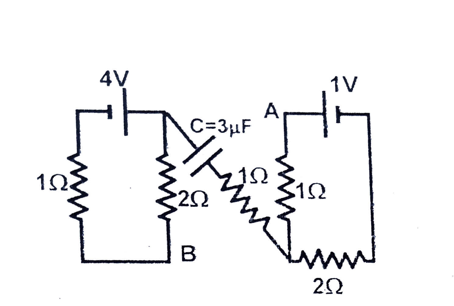
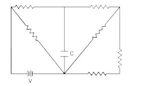
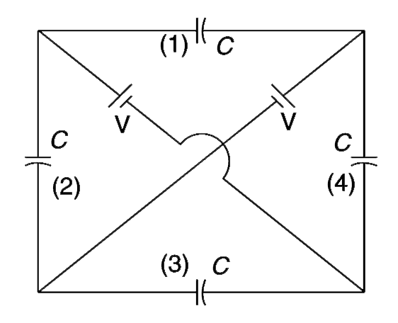
In the circuit shown in the adjacent figure, the batteries are ideal. The charge on the capacitor C is
10μC
20μC
30μC
zeo
The correct Answer is:D
No current will flow through the capacitor, so charge will be zero
Topper's Solved these Questions
- TEST PAPERSBook:FIITJEEChapter:TEST PAPERSExercise:PHYSICS
Explore 747 Videos
- SIMPLE HARMONIC MOTIONBook:FIITJEEChapter:SIMPLE HARMONIC MOTIONExercise:Assignment Problems (Objective) (Level-II)
Explore 20 Videos
- WORK, ENERGY AND POWER Book:FIITJEEChapter:WORK, ENERGY AND POWER Exercise:COMPREHENSIONS ( Comprehension-II)
Explore 5 Videos
Similar Questions
Knowledge Check
In the figure shown : (All batteries are ideal)
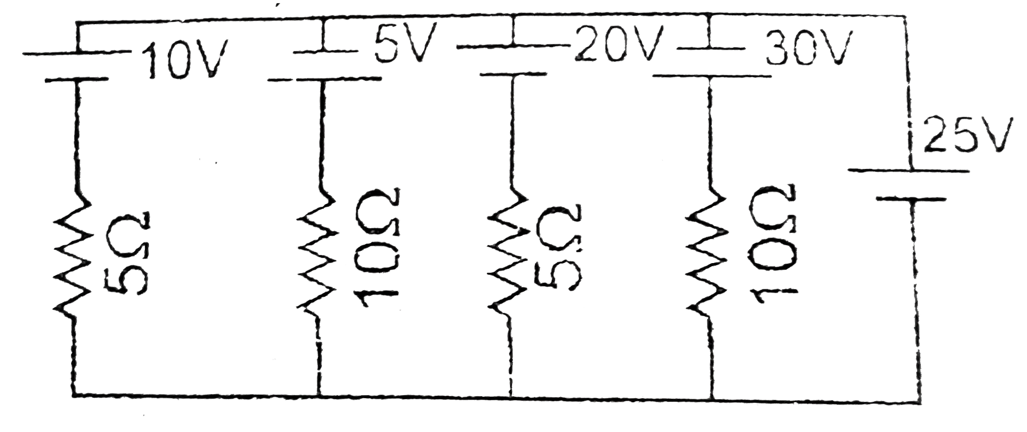 Acurrent through 25 V cell is 20 ABcurrent through 25 V cell is 12.5 ACpower supplied by 20 V cell is 20 WDpower supplied by 20 V cell is -20 W
Consider the circuit shown in the figure below :
All the resistors are identical. The charge stored in the capacitor, once it is fully charged, isA0B513CVC23CVD58CVIn the circuit shown in the figure, the total charge is 750μC and the voltage across capacitor C2 is 20 V. Then the charge on capacitor C2 is:
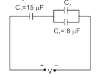 A650μCB450μCC590μCD160μC
In the circuit shown in figure-3.244, the battery is an ideal one with emf V. The capacitor is initially uncharged. The switch S is closed at time t=0.
(a) Find the charge Q on the capacitor at time l
(b) Find the current in branch AB at time just after closing the switch.
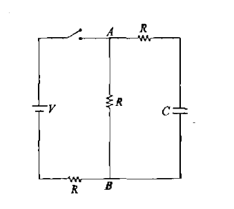
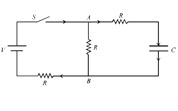
View SolutionIn the circuit shown in Figure, the battery is an ideal one, with emf V. The capacitor is initially uncharged. The switch S is closed at time t = 0 .
(a) Find the charge Q on the capacitor at time t.
(b) Find the current in AB at time t. What is its liniting value as t→∞:
 .
.
View SolutionIn the circuit shown in the figure all the capacitors have capacitance C.
(a) Find the charge on capacitors marked as 1 and 2 when a battery of emf V is connected across points A and B.
(b) Find the equivalent capacitance across points C and D marked in the Figure.
(c) Find the equivalent capacitance across points E and G.
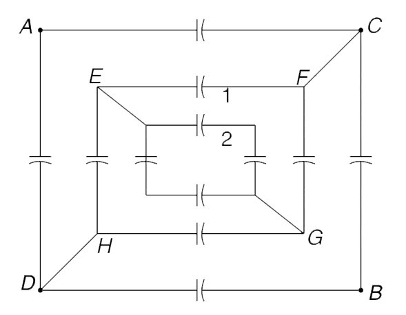
View SolutionIn the circuit shown in the figure, find charge on each capacitor.
View SolutionIn the circuit shown in the figure, in steady state:

The charge on 5μF capacitor is
View Solution


