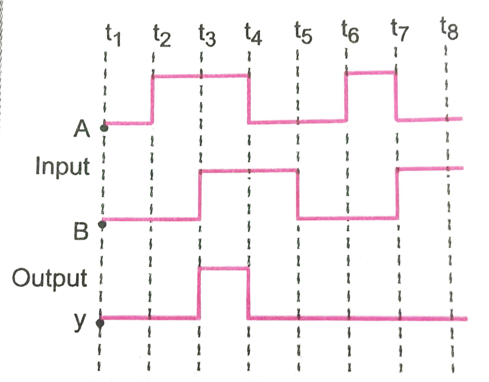
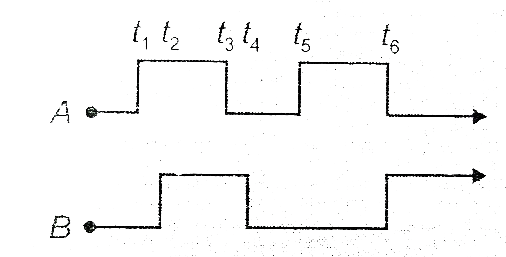
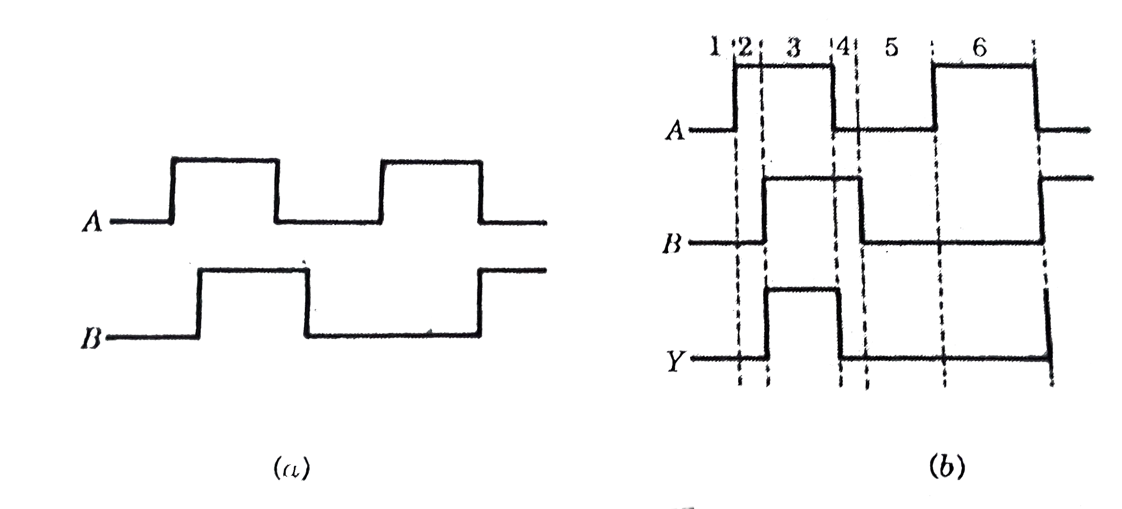
The Fig shown input waveforms A and B to a logic gate. Draw the output waveform for an OR gate. Write the truth table for this logic gate and draw its logic symbol.
A

B

C
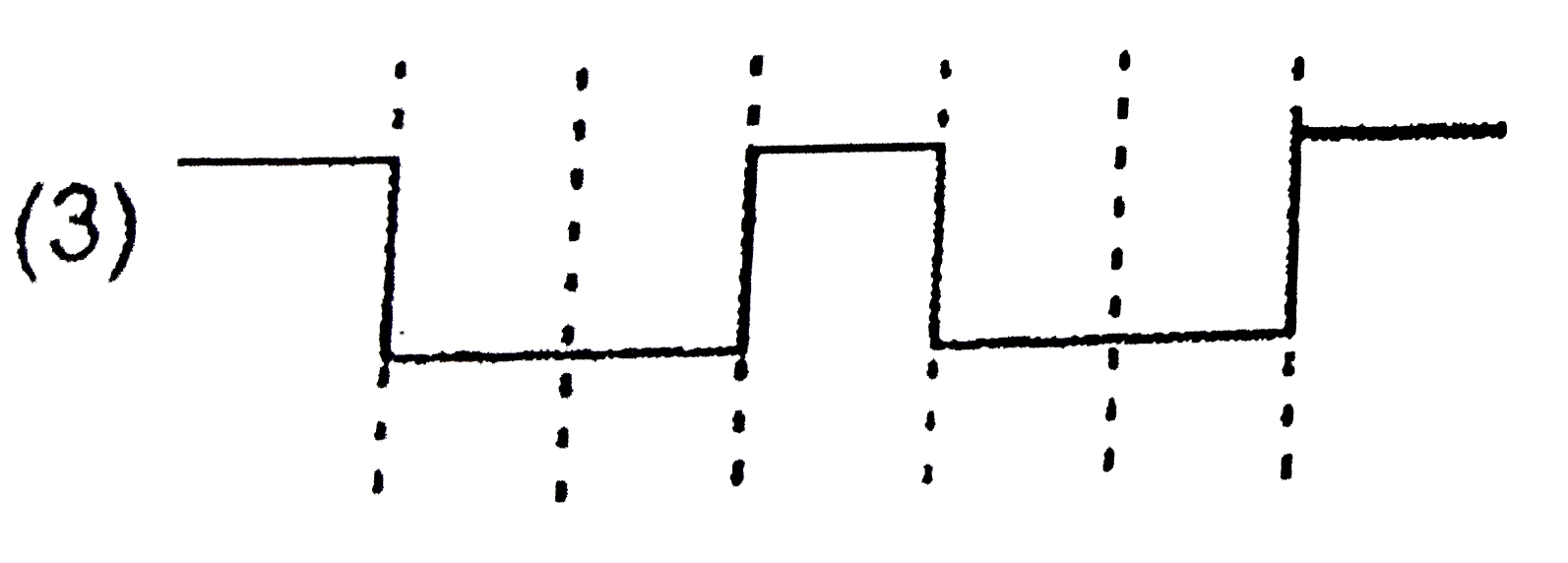
D
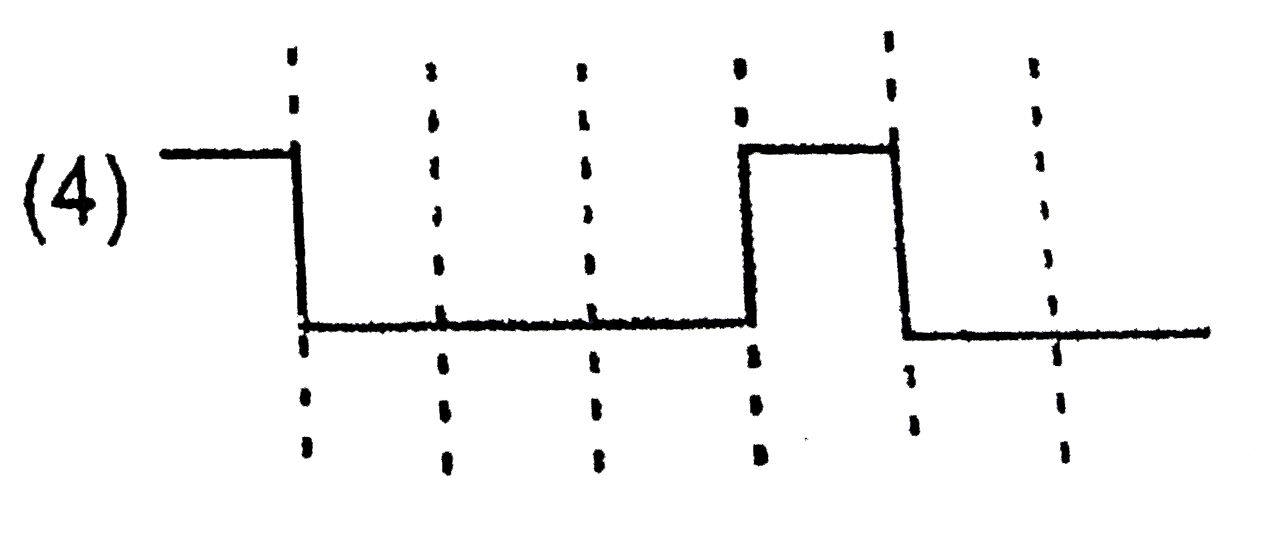
Video Solution
Text Solution
The correct Answer is:D
If lattice constant of semiconductor is decreased, then EC and EV decrease but Eg increase.
|
Topper's Solved these Questions
Similar Questions
Knowledge Check
The truth table of a logic gate is a table
Agiving only the true numbersBrejecting only the wrong numbersCgiving the relation between the input and output variables of a logic gateDwhich gives all the possible input logic levels and the corresponding resultant logic levels in the output
Write the output waveform of the OR gate for the inputs
View SolutionShow the output waveform of OR gate for the following input waveforms of A and B
View SolutionShow the output waveform of OR gate for the following input waveforms of A and B

View Solution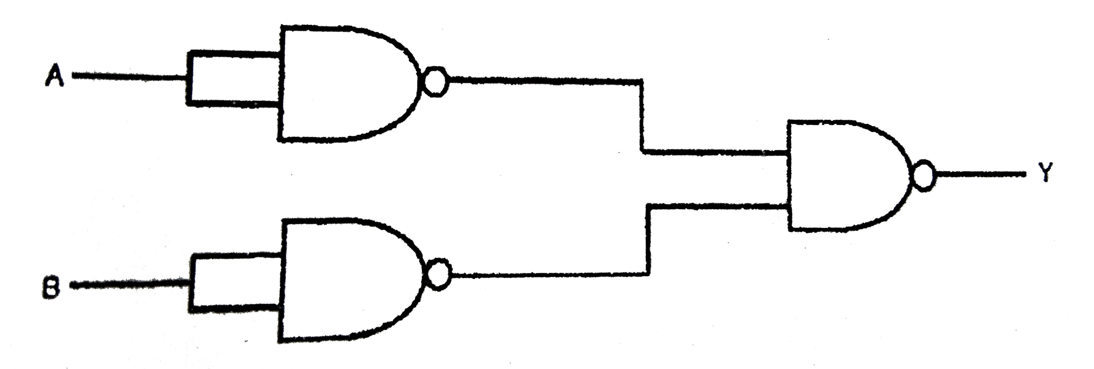
Draw the truth table for the logic gate arrangement shown in the figure.
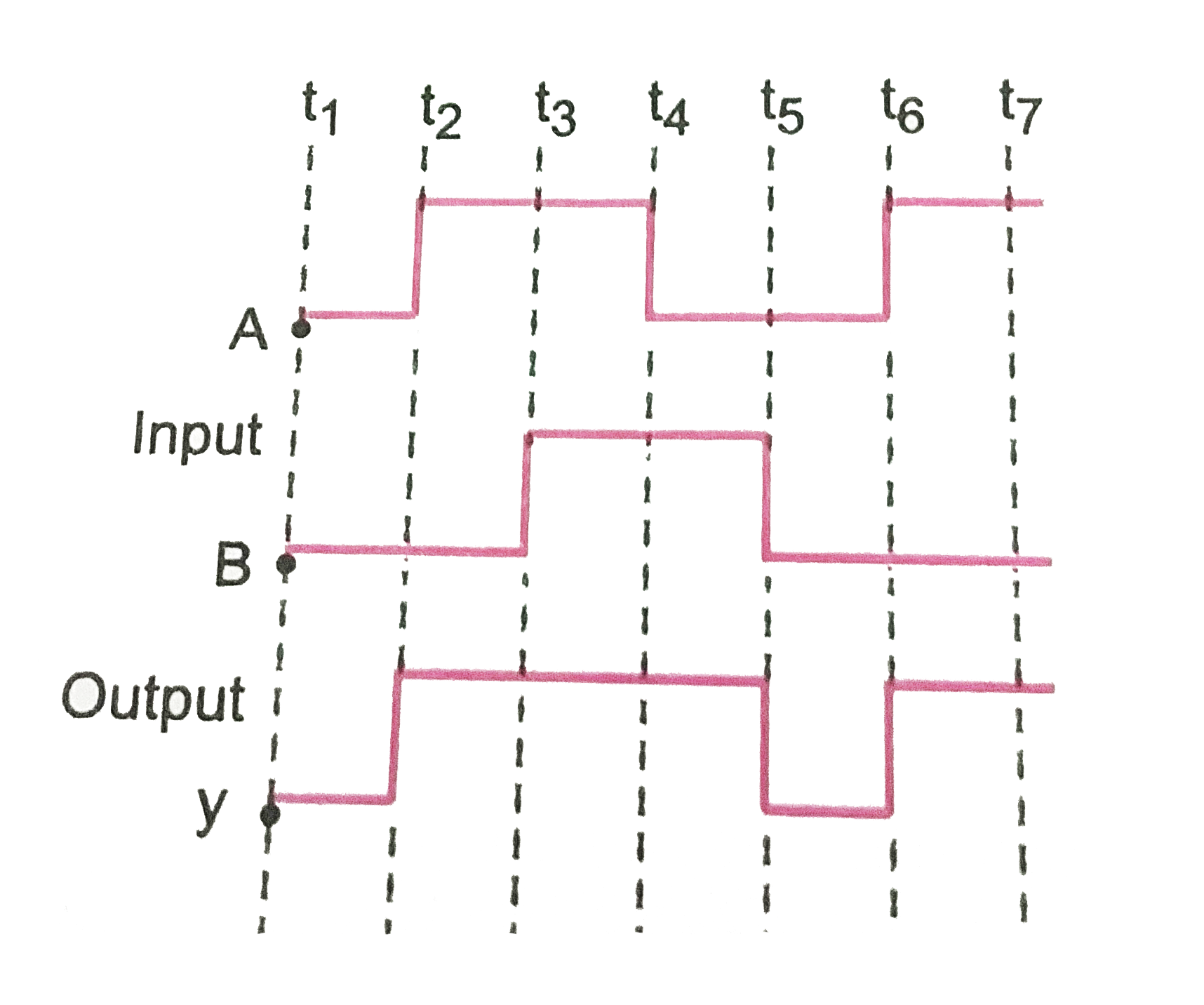
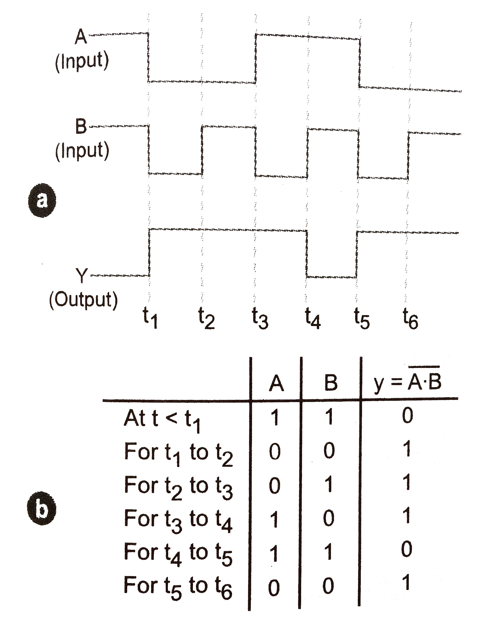
View SolutionThe following Fig. shows the input waveforms (A,B) and the output waveform (y) of a gate. Identify the gate and write its truth table.
View Solution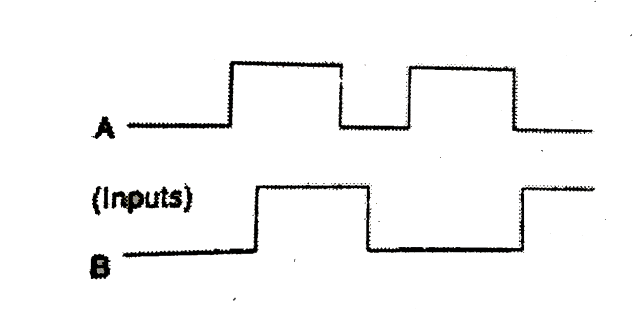
Give the logic symbol for an OR gate. Draw the output wave form for input wave forms A and B for this gate.
View SolutionTwo input waveforms A and B shown in fig (a) are applied to an AND gate.Write the output waveform.
View Solution

