The arrangement for a mirror experiment is shown in figure. S is a point source of frequency 6×10¹⁴Hz. D and C represent the two ends of a mirror placed horizontally and LOM represents the screen.

Determine the width of the region where the fringes will be visible
4cm
6cm
2cm
3cm
The correct Answer is:C

Fringes will be observed in the region between P1 and P2 because the reflected rays lie only in this region. From similar triangles : BDS1asndS1P2A .
AP2BS1=AS1BD,BS1=BS=1mm=10−1cm
AP2=AS1×BS1BD=200×0.15=4cmAP2=4cm
Similarly, BCS1 and S1P1A are similar triangles
AP1BS1=AS1BDAP1=AS1×BS1BD=200×0.110=2cm
Width of the region where fringes observed is
P1P2=AP2−AP2=4−2=2cm,P1P2=2cm
Topper's Solved these Questions
- WAVE OPTICSBook:NARAYNAChapter:WAVE OPTICSExercise:LEVEL - I(H.W)
Explore 20 Videos
- WAVE OPTICSBook:NARAYNAChapter:WAVE OPTICSExercise:LEVEL - II(H.W)
Explore 19 Videos
- WAVE OPTICSBook:NARAYNAChapter:WAVE OPTICSExercise:LEVEL - V
Explore 37 Videos
- SEMICONDUCTOR ELECTRONICSBook:NARAYNAChapter:SEMICONDUCTOR ELECTRONICSExercise:ADDITIONAL EXERCISE (ASSERTION AND REASON TYPE QUESTIONS :)
Explore 19 Videos
Similar Questions
Young's double slit experiment is perfor-med inside water (μ=43) with light of frequency 6×10¹⁴ Hz. If the slits are separated by 0.2 mm and the screen kept 1 m from the slits, find the fringe width. Using the same set-up, what will the fringe width be if the experiment is performed in air?
View SolutionIn Young's double slit experiment , the light has a frequency of 6×10¹⁴Hz and the distance between the centres of adjacent fringes is 0.75mm. If the screen is 1.5m away, what is the distance between the slits ?
View Solution
Knowledge Check
The arrangement for a mirror experiment is shown in figure. S is a point source of frequency 6×10¹⁴Hz. D and C represent the two ends of a mirror placed horizontally and LOM represents the screen.

Find the fringe width of the fringe pattern ?A0.05cmB0.25cmC0.01cmD0.1cmThe arrangement for a mirror experiment is shown in figure. S is a point source of frequency 6×10¹⁴Hz. D and C represent the two ends of a mirror placed horizontally and LOM represents the screen.

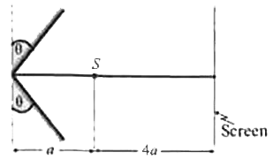
Calculate the number of fringesA10B20C30D40There are two plane mirrors. They are mutually inclined as shown in figure. S is a source of monochromatic light of wavelength λ. The reflected beam interfere and fringe pattern is obtained on the screen. If θ is small, the fringe width will be :
 Aλ/θB3λ/2θC2λ/3θDnone of these
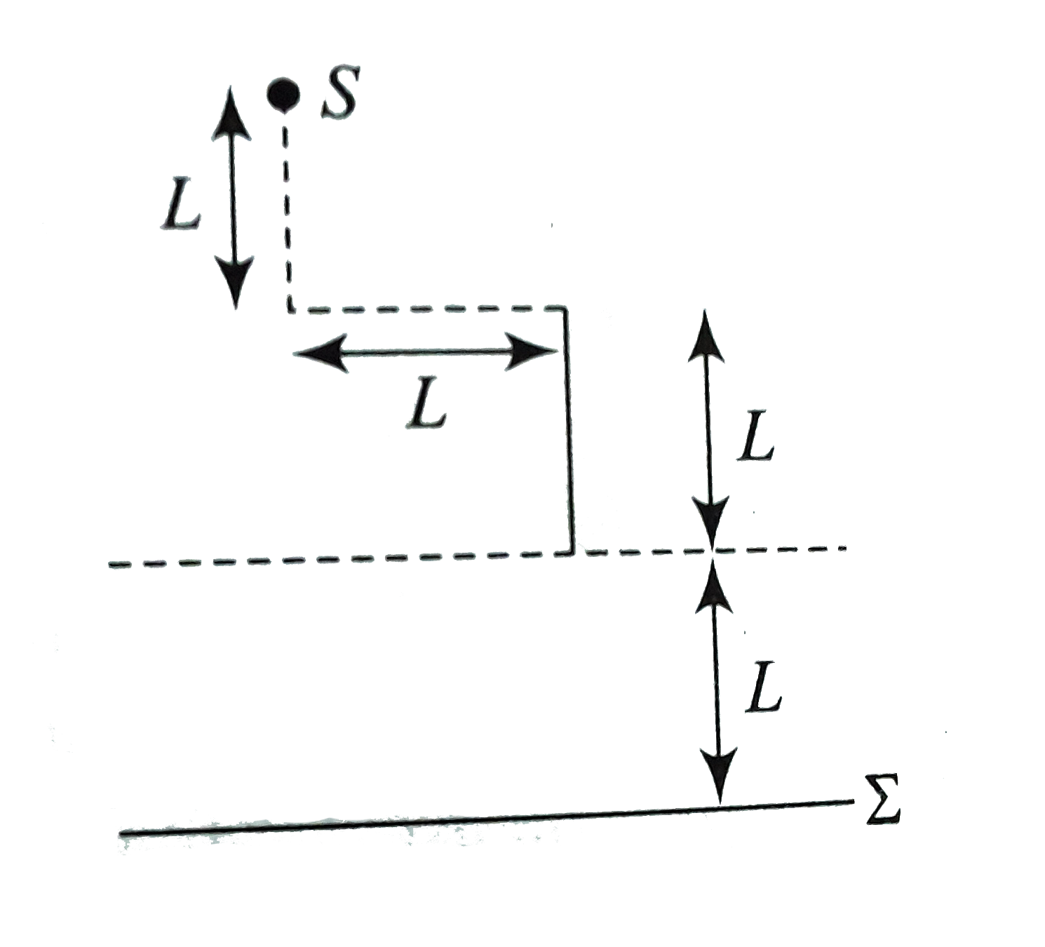
A point source of light is placed in front of a plane mirror as shown in Figure.
Determine the length of reflected path of light on the screen Σ

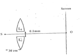
View SolutionTwo independent light sources are always incoherent. This is because phase of light emitted is random and phase difference, at any point, changes very rapidly with time. So as to obtain observable interference, we require coherent sources which emit light of same wavelength such that phase difference at any point does not change with time. In different interference experiments, the method to obtain two coherent sources could be different. In Fresnel's biprism experiment, two virtual images of a real source, which are formed due to refraction at the biprism, act as coherent source. In Lloyd’s mirror experiment, a real source and its virtual image formed due to reflection at a plane mirror act as coherent source. Two images of a source or a source and its image are coherent because of their phase correlation. It is also possible to obtain coherent sources by forming two images of a point source in the following manner.As shown in the figure, S is a monochromatic point source. A thin circular lens is cut into two identical halves L, and L2 by a plane passing through a diameter. L1 is kept above the axis and L2 below it is in a symmetrical manner such that the gap between the two is 0.1 mm. Each forms an image Qf the source and the two images, say, Si and S2 , act as coherent sources. Superposition of waves from these coherent sources will result in observable interference and a pattern can be obtained on a screen.The lens which has been cut to from L, and L2 is made of a material of refractive index 1.5 for the wavelength emitted by the source S. Radius of curvature of each surface of the lens is 18 cm. Source S is 30 cm along the axis fro Li and L2 . It is found that smallest distance from O along the screen at which intensity is half of the maximum intensity is 0.1 mm. It is also observed that the highest order of maximum intensity in the interference patter is 416.
Q Fringe width is nearly

View Solution_S01_029_Q01.png)
In the figure shown S is a point monochromatic light source of frequency 6×10¹⁴Hz.M is a concave mirror of radius of curvature 20 cm and L is a thin converging lens of focal length 3.75 cm AB is the principal axis of M and L.
Light reflected from the mirror and refracted from the lens in succession reaches the screen. An interference pattern is obtained on the screen by this arrangement.
Q. Fringe width is
View Solution_S01_028_Q01.png)
In the figure shown S is a point monochromatic light source of frequency 6×10¹⁴Hz.M is a concave mirror of radius of curvature 20 cm and L is a thin converging lens of focal length 3.75 cm AB is the principal axis of M and L.
Light reflected from the mirror and refracted from the lens in succession reaches the screen. An interference pattern is obtained on the screen by this arrangement.
Q. Distance between two coherent sources whichmakes interference pattern on the screen is
View SolutionA monochromatic light source S of wavelength 440 nm is placed slightly above a plane mirror M as shown . Image of S in M can be used as a virtual source to produce interference fringes on the screen. The distance of source S from O is 20.0 cm, and the distance of screen from O is 100.0 cm (figure is not to scale). If the angle θ=0.50×10⁻³ radians, the width of the interference fringes observed on the screen is –

View Solution
